Sub-control phase change heat transfer system and sub-control phase change heat transfer method

A phase-change heat and controller technology, applied to indirect heat exchangers, heat exchange equipment, lighting and heating equipment, etc., can solve the problems of limited emptying capacity, poor adjustment characteristics, and large control hysteresis, and achieve improved Reliability and precision, flexible layout design, and improved adaptability

Inactive Publication Date: 2012-08-01
INST OF PROCESS ENG CHINESE ACAD OF SCI +2
View PDF8 Cites 15 Cited by
  • Summary
  • Abstract
  • Description
  • Claims
  • Application Information

AI Technical Summary

Problems solved by technology

There are also phase change heat systems that use heat release devices or heat absorption devices to control phase change parameters by fluid recirculation. Not only the adjustment characteristics are not good, the control lag is large, and the equipment investment is large, which increases the difficulty of equipment site layout. Cycling also significantly increases the energy consumption of the system
In addition, the traditional phase-change heat technology adopts the return water method of gravity self-flow, which inevitably requires the position of the condensing pipe to be higher than the evaporating pipe, which brings great difficulties to on-site installation and technical transformati...

Method used


Image

  • Sub-control phase change heat transfer system and sub-control phase change heat transfer method

Examples


Embodiment Construction

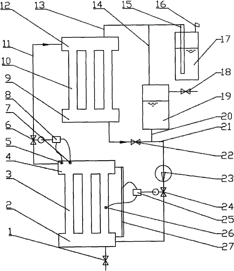
[0040] An embodiment of the split-controlled phase-change heat system of the present invention is as attached figure 1 As shown, the main components include: liquid discharge valve 1; heat-absorbing lower header 2; heat-absorbing tube bundle 3; heat-absorbing upper header 4; gas pressure sensor 5; airflow regulating valve 6; gas temperature sensor 7; airflow regulating valve Controller 8; exothermic lower header 9; exothermic tube bundle 10; steam pipe 11; exothermic upper header 12; breathing pipe 13; gas side connecting pipe 14 of liquid storage tank 19; Liquid seal box 17; rehydration valve 18; liquid storage tank 19; liquid side communication pipe 20 of liquid storage tank 19; condensate pipe 21; discharge valve 22; pump 23; liquid flow regulating valve 24; liquid flow regulating valve controller 25 ; Wall temperature sensor 26; Liquid level sensor 27.

[0041] In this embodiment, the heat-absorbing device includes a heat-absorbing upper header 4, a heat-absorbing lower h...


PUM


Abstract

The invention relates to a sub-control phase change heat transfer system. The sub-control phase change heat transfer system comprises a heat absorption device and a heat release device which are mutually communicated through a vapor pipe (11) and a condensed fluid pipe (21) so as to form a sub-control phase change heat transfer loop. The sub-control phase change heat transfer system is characterized by comprising an airflow regulating valve (6), an airflow regulating valve controller (8), a liquid flow regulating valve (24) and liquid flow regulating valve controller (25), wherein the airflow regulating valve (6) is arranged in the pipeline of the vapor pipe (11) and the opening of the airflow regulating valve (6) is controllable; and the liquid flow regulating valve (24) is arranged in the pipeline of the condensed fluid pipe (21) and the opening of the liquid flow regulating valve (24) is controllable. The invention also provides a sub-control heat transfer method. In the method, the phase change heat transfer parameters of the heat absorption device and the heat release device are respectively independently controlled.

Description

technical field [0001] The invention belongs to the technical field of safe and controllable enhanced heat transfer, and is particularly suitable for use in the fields of waste heat recovery and utilization of boiler flue gas and production process tail gas. Background technique [0002] In domestic and foreign enhanced heat transfer technologies and technologies dedicated to waste heat recovery and utilization, many high-efficiency phase-change heat transfer technologies have been developed by utilizing the characteristics of high heat transfer coefficient and uniform temperature of vapor condensation and liquid boiling evaporation. In terms of reducing boiler exhaust gas temperature, recovering waste heat and improving thermal efficiency, heat pipes or other phase conversion heat technologies are often used to control the corrosion and ash deposition speed of the heating surface on the flue gas side through different technical solutions, and better results have been achieve...

Claims


Application Information

Patent Timeline
IPC IPC(8): F28D15/02F28F27/00
Inventor 郝江平高士秋许光文闫润生
Owner INST OF PROCESS ENG CHINESE ACAD OF SCI
Why Eureka
Try Eureka