Laser radar visibility meter and transceiving coaxial optical system thereof

A visibility meter and lidar technology, applied in optics, optical components, radio wave measurement systems, etc., can solve problems such as changes in the parallelism of two axes, detection blind spots in non-coaxial structures, distortion of measurement data, etc., and achieve volume reduction. , to avoid the leveling problem of the transmitting and receiving optical paths, and the effect of weight reduction

Inactive Publication Date: 2012-08-01
杨少辰
View PDF7 Cites 14 Cited by
  • Summary
  • Abstract
  • Description
  • Claims
  • Application Information

AI Technical Summary

Problems solved by technology

[0003] At present, the laser radar visibility meter commonly used at home and abroad adopts the non-coaxial design of the transmitting beam and the receiving beam. The transmitting laser beam of this structure will not pose a threat to the signal detector, but there is a problem of balancing the optical axis of the transmitting beam and the receiving beam. Problem, under the influence of ambient temperature, the parallelism of the two axes may change, resulting in distortion of the measured data
In addition, there is a detection blind area in the non-coaxial structure, and the influence of the geometric overlap factor needs to be considered in the measurement

Method used


Image

  • Laser radar visibility meter and transceiving coaxial optical system thereof
  • Laser radar visibility meter and transceiving coaxial optical system thereof
  • Laser radar visibility meter and transceiving coaxial optical system thereof

Examples


Embodiment Construction

[0018] In order to make the object, technical solution and advantages of the present invention clearer, the present invention will be further described in detail below in conjunction with the accompanying drawings and embodiments. It should be understood that the specific embodiments described here are only used to explain the present invention, not to limit the present invention.

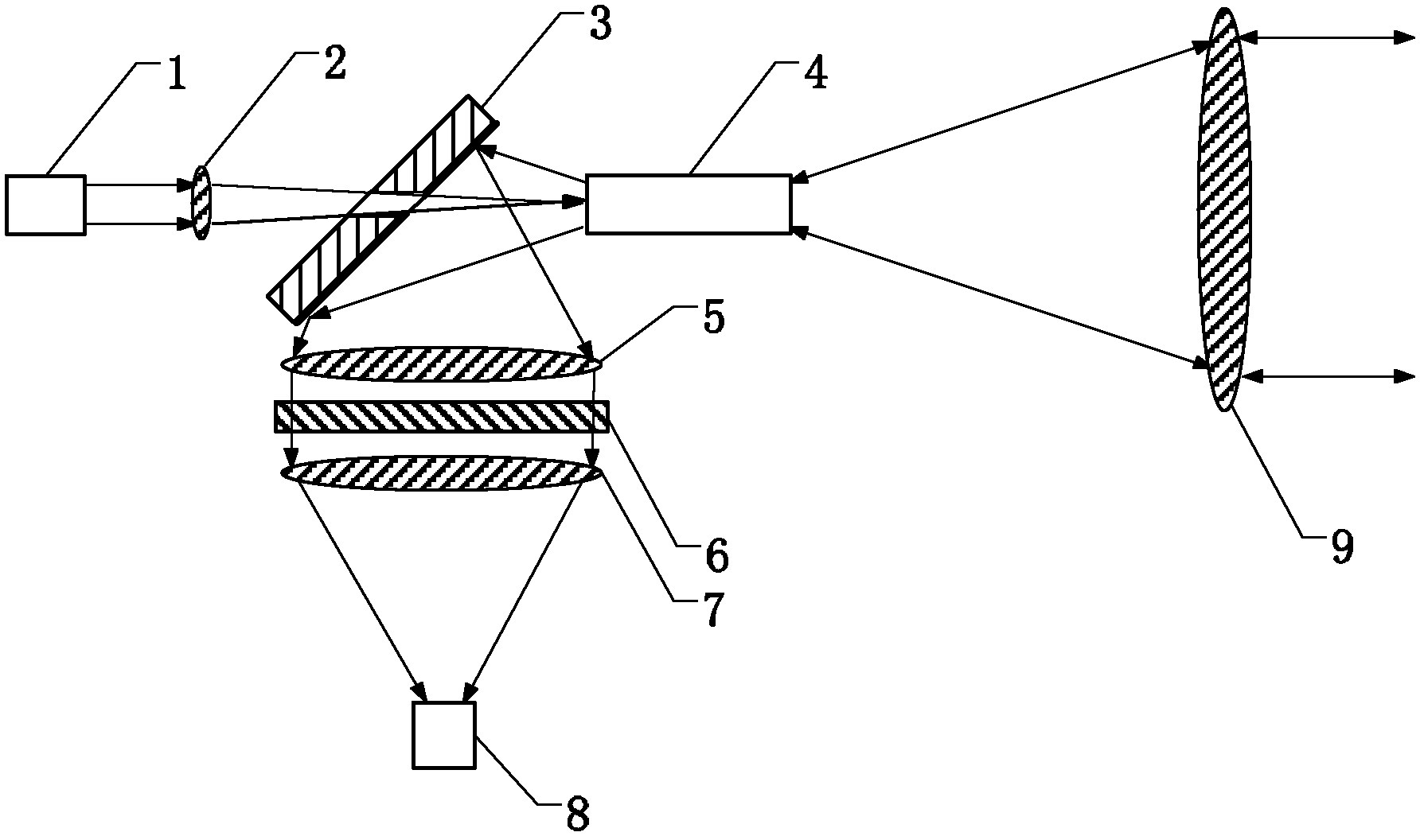
[0019] An embodiment of the present invention provides a transceiver coaxial optical system of a laser radar visibility meter, such as figure 1 and figure 2 As shown, the optical system is sequentially provided with a focal length f on the subsequent optical path of the outgoing beam of the laser 111 introduced by the input fiber 1 The lens 2 and the reflector 3 with a small hole in the center, the laser output beam is focused by the lens 2, and coupled into the transceiver optical fiber 4 after passing through the small hole in the center of the reflector 3. The small hole in the center of the ...


PUM


Abstract

The invention relates to a laser radar visibility meter and a transceiving coaxial optical system of the laser radar visibility meter. A lens and a reflector are sequentially arranged on a subsequent light path of an outgoing beam of a laser, the center of the reflector is provided with a small hole, the outgoing beam of the laser is focused by the lens, passes through the small hole in the center of the reflector, then is coupled in a transceiving optical fiber and is guided into a telescope system for emission, an atmosphere return signal enters the transceiving optical fiber again through the telescope system, the beam is coupled by a lens group and a light filter into the transceiving optical fiber after being reflected by the reflector, the transceiving optical fiber is connected with a detector, so that the signal acquisition is fulfilled. The transceiving coaxial optical system provided by the invention can effectively avoid the problem that a non-coaxial laser radar visibility meter is level with a transceiving light path, and is not affected by any geometrical overlap factors; in addition, the transceiving coaxial structure enables the volume of the laser radar visibility meter to be small, the weight to be light and the structure to be more compact.

Description

technical field [0001] The invention relates to the technical field of laser equipment, in particular to the transceiver optical system of a laser visibility meter. Background technique [0002] The lidar visibility meter has the advantages of small size and high measurement accuracy, and can realize multi-angle, all-weather detection, and obtain horizontal and oblique visibility information, which is of great significance for improving aviation safety. [0003] At present, the laser radar visibility meter commonly used at home and abroad adopts the non-coaxial design of the transmitting beam and the receiving beam. The transmitting laser beam of this structure will not pose a threat to the signal detector, but there is a problem of balancing the optical axis of the transmitting beam and the receiving beam. The problem is that under the influence of ambient temperature, the parallelism of the two axes may change, resulting in distortion of the measured data. In addition, no...

Claims


Application Information

Patent Timeline
Patent Type & Authority Applications(China)
IPC IPC(8): G01S17/95G01N21/01G02B23/00G02B7/02G02B1/11
CPCY02A90/10
Inventor 孙东松杨少辰
Owner 杨少辰
Why Eureka
Try Eureka