
Automatic generation method of plunge milling toolpath for corner features

An automatic generation and plunge milling technology, applied in special data processing applications, instruments, electrical digital data processing, etc., can solve the problem that the processing method does not take into account the machining accuracy of the machining allowance, the processing of complex surfaces, the correctness of the generated tool path, The reliability and practicability are not strong, and the free-form surface of the corner surface is not considered, so as to achieve the effect of shortening the production cycle, high accuracy and fast speed

Active Publication Date: 2012-08-08
SUZHOU MACHINING PRECISION ELECTRONICS
View PDF6 Cites 32 Cited by
  • Summary
  • Abstract
  • Description
  • Claims
  • Application Information

AI Technical Summary

Problems solved by technology

The disadvantages of this method are: (1) It does not take into account the situation in the actual machining. The tool radius of the plunge milling in the actual machining should be greater than or equal to the radius of the corner, so there is no situation that the position of the plunge milling cutter is in the arc surface of the corner; (2) The method of calculating the direction of the tool axis does not take into account the fact that the corner surface is a free-form surface, and there is an error in the direction of the tool axis calculated for the corner surface of the free-form surface; (3) The margin problem in actual processing is not considered, that is, the Accurately ensure the allowance of the side and bottom webs for plunging milling; (4) The distribution of tool points in the axial direction is not discussed. If only one layer of tool points is used, the three-axis corner plunging milling can be properly operated by CAM software The web margin can be ensured by defining the plunge-milling depth, but the plunge-milling depth cannot be directly obtained for the five-axis machining corner, and it needs to be obtained through certain calculations; (5) The plunge-milling method has certain requirements in technology, which must be Under the premise of meeting these process requirements, the final generated plunge milling tool path is correct and practical
[0006] The existing automatic generation method of plunge milling tool path has not considered the actual production situation of the enterprise and the processing technology of the parts, and the processing method has not considered the problems of ensuring the machining accuracy of the machining allowance and the processing of complex surfaces, so that it can generate the tool path The correctness, reliability and practicability are not strong

Method used


Image

  • Automatic generation method of plunge milling toolpath for corner features
  • Automatic generation method of plunge milling toolpath for corner features
  • Automatic generation method of plunge milling toolpath for corner features

Examples


Embodiment Construction

[0049] The technical solution of the present invention will be described in detail below in conjunction with the accompanying drawings.

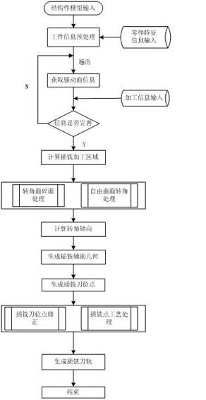
[0050] figure 1 It is a flow chart of the method for automatically generating corner feature plunge milling tool paths of the present invention. As shown in the figure, the following steps are included:

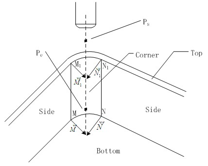
[0051] The processing feature involved in the invention is the cavity corner of the aircraft structure. Input the structural part model into the system to preprocess the parts. The input of part feature information can be automatically read into the feature information list of the part, or by manually selecting the feature of the part to obtain the driving geometry related to the corner. The relevant driving geometry of the plunge milling corner includes the corner surface, the side surface connected to the corner surface, the top surface, the web surface, such as figure 2 shown.

[0052] Input the plunge milling processing information...


PUM


Abstract

The invention discloses an automatic generation method of a plunge milling toolpath for corner features, and belongs to the technical field of CAD (Computer-Aided Design) / CAPP (Computer-Aided Process Planning) / CAM (Computer-Aided Manufacturing). The automatic generation method comprises the following steps: firstly, conducting the pretreatment such as part selection, part feature information read-in and the like; secondarily, obtaining geometric surfaces needed in corner processing from the part feature information, and automatically calculating the corner plunge milling area geometric auxiliary point, the axial corner geometric auxiliary point and the plunger milling generation geometric auxiliary point according to information such as the plunger milling processing redundancy, the radius of a cutting tool in the former process or work step as well as the rough processing redundancy and the like; and finally, generating the plunger milling tooth-paths of all part corners through the auxiliary points automatically. The plunge milling tool-paths for corners, generated through the invention, are high in speed and high in accuracy rate, and can process a corner in a large processing area, a corner containing scattered surfaces, a five-axis corner, and a corner of which the proximal surface is a big-curvature side surface, so that the method solves the problem that the manual corner plunger milling programming process is trivial and complicated and low in efficiency. Through the invention, a good effect on plunger milling of corners of an aircraft structural part can be obtained.

Description

technical field [0001] The invention relates to a method for automatically generating a corner-featured plunge-milling tool track, in particular to a method for generating a corner-characteristic plunge-milling tool track for complex structural parts of an aircraft, which belongs to CAD (Computer Aided Design) / CAPP (Computer Aided Process Design) / CAM (Computer Aided Manufacturing) technology field. Background technique [0002] The number of cavity corners of aircraft structural parts is large, and the programming workload is the largest and the time-consuming is the longest. With the general side milling method, the processing efficiency is low, and the manual programming workload is heavy. The plunge milling method, also known as the Z-axis milling method, is one of the most effective processing methods to achieve high cutting rate metal cutting. For difficult-to-machine materials and machining with a large overhang length of the tool, the machining efficiency of the pl...

Claims


Application Information

Patent Timeline
IPC IPC(8): G06F17/50
Inventor 李迎光刘长青刘旭王伟李海黎明
Owner SUZHOU MACHINING PRECISION ELECTRONICS
Learn More