Radar safety guard
A radar protective cover and protective layer technology, which is applied to the radiation unit cover and other directions, can solve the problems of low surface brightness, insufficient corrosion resistance, affecting the service life of the radar protective cover, etc. The effect of the service life
- Summary
- Abstract
- Description
- Claims
- Application Information
AI Technical Summary
Problems solved by technology
Method used
Image
Examples
Embodiment 1
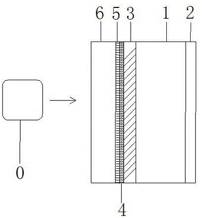
[0025] A radar protective cover with a thickness of 5 mm is composed of a polycarbonate base and a transparent polycarbonate front cover 1 connected with the polycarbonate base through an adhesive, and is composed of figure 1 As shown, the side of the transparent polycarbonate front cover 1 facing away from the radar 0 is sequentially provided with a topcoat layer 2 with a thickness of 5 μm, and the side of the transparent polycarbonate front cover 1 facing the radar 0 is sequentially provided with a thickness of 5 μm. A primer layer 3 with a thickness of 5 μm, a hot stamping black film layer 4 with a thickness of 0.1 μm, a vacuum-plated nano-metal layer 5 with a thickness of 0.1 μm, and a paint protective layer 6 with a thickness of 5 μm. Among them, the vacuum-plated nano-metal layer 5 and the paint protection layer 6 both have a radar penetration attenuation of no more than 0.2dB. The paint protection layer 6 is an acrylic polyurethane coating with a thickness of 5 μm, whic...
Embodiment 2
[0027] A radar protective cover with a thickness of 7.5 mm is composed of a polycarbonate base and a transparent polycarbonate front cover 1 connected with the polycarbonate base through secondary injection molding. figure 1As shown, the side of the transparent polycarbonate front cover 1 facing away from the radar 0 is provided with a topcoat layer 2 with a thickness of 25 μm, and the side of the transparent polycarbonate front cover 1 facing the radar 0 is sequentially provided with a layer of 25 μm in thickness. A primer layer 3 with a thickness of 25 μm, a printed color film layer 4 with a thickness of 1 μm, a vacuum-plated nano-metal layer 5 with a thickness of 1 μm, and a paint protection layer 6 with a thickness of 25 μm, wherein the vacuum-plated nano-metal layer 5 and the paint protection layer 6 have No more than 0.2dB radar back and forth penetration attenuation. The paint protection layer 6 is mainly used to protect the nano-metal layer 5 and make the protective co...
Embodiment 3
[0029] A radar protective cover with a thickness of 5 mm is composed of a polycarbonate base and a transparent polycarbonate front cover 1 connected with the polycarbonate base through secondary injection molding. figure 1 As shown, the side of the transparent polycarbonate front cover 1 facing away from the radar 0 is provided with a topcoat layer 2 with a thickness of 15 μm, and the side of the transparent polycarbonate front cover 1 facing the radar 0 is sequentially provided with a layer of 15 μm in thickness. A primer layer 3 of 15 μm, a printed color film layer 4 with a thickness of 0.5 μm, a vacuum-plated nano-metal layer 5 with a thickness of 0.5 μm, and a paint protection layer 6 with a thickness of 10 μm, wherein the vacuum-plated nano-metal layer 5 and paint protection layer 6 It has no more than 0.2dB radar penetration attenuation back and forth. The coating protection layer 6 is mainly used to protect the nano-metal layer 5 and make the protective cover resistant ...
PUM
 Abstract
Description
Claims
Application Information
 - R&D
- Intellectual Property
- Life Sciences
- Materials
- Tech Scout
- Unparalleled Data Quality
- Higher Quality Content
- 60% Fewer Hallucinations
Browse by: Latest US Patents, China's latest patents, Technical Efficacy Thesaurus, Application Domain, Technology Topic, Popular Technical Reports.
© 2025 PatSnap. All rights reserved.Legal|Privacy policy|Modern Slavery Act Transparency Statement|Sitemap|About US| Contact US: help@patsnap.com


