Boost two-way voltage balance converter

A technology of balance converter and bidirectional voltage, which is applied in the direction of adjusting electric variables, converting DC power input to DC power output, instruments, etc. It can solve the problems of unidirectional flow of power and failure to realize bidirectional flow of power, so as to improve efficiency and solve the problem of The effect of series electrolytic capacitor voltage equalization to meet the requirements of input voltage balance

Inactive Publication Date: 2014-05-07
HUAIHAI INST OF TECH
View PDF5 Cites 0 Cited by
  • Summary
  • Abstract
  • Description
  • Claims
  • Application Information

AI Technical Summary

Problems solved by technology

[0003] The technical solution disclosed in the Chinese patent application 201110100205.3 invented by the inventor can only realize the one-way flow of power and construct a center line, and cannot realize the two-way flow of power, etc.

Method used


Image

  • Boost two-way voltage balance converter
  • Boost two-way voltage balance converter
  • Boost two-way voltage balance converter

Examples


Embodiment 1

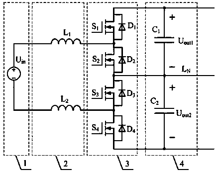
[0039] Embodiment 1, with reference to figure 1 , a step-up dual-voltage balance converter, which includes an input terminal DC voltage source 1, a step-up inductor circuit 2, a half-bridge circuit 3, and an output filter circuit 4;

[0040] The boost inductor circuit 2 includes a first boost inductor L 1 and the second boost inductor L 2 , the first boost inductor L 1 One end of and the input DC voltage source U in The positive terminal is connected, the second boost inductor L 2 One end of and the input DC voltage source U in connected to the negative terminal;

[0041] The half-bridge circuit 3 includes a first power switch tube S 1 , the second power switch tube S 2 , the third power switch tube S 3 , the fourth power switch tube S 4 and the first freewheeling diode D 1 , the second freewheeling diode D 2 , the third freewheeling diode D 3 , the fourth freewheeling diode D 4 , the first power switch S 1 drain with the first freewheeling diode D 1 The cathode...

Embodiment 2

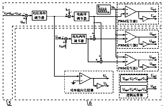
[0043] Embodiment 2, with reference to figure 2 , the step-up bidirectional voltage balance converter described in embodiment 1 can be controlled by an output voltage outer loop controller 5 and an output voltage inner loop balance controller 6;

[0044] Described output voltage outer loop controller 5 comprises voltage outer loop regulator, current loop regulator, PWM generator 1, the output of voltage outer loop regulator is used as the input reference value of current loop regulator, the output of current loop regulator Generate and control the first power switch tube S through the PWM generator I 1 The drive signal U gs1 and the second power switch S 2 The drive signal U gs2 ;

[0045] The described output voltage inner loop balance controller 6 includes a voltage inner loop regulator, a power flow direction comparator, a PWM generator II, a PWM generator III, a logic operator, and the output of the voltage inner loop regulator is connected with the output voltage out...

Embodiment 3

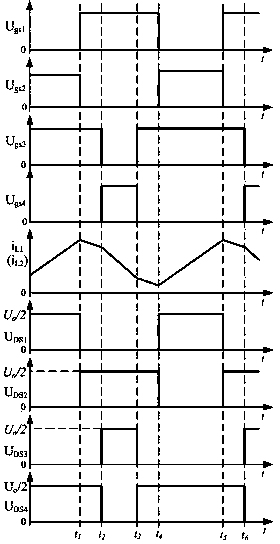
[0047] Embodiment 3, with reference to Figure 3-10 , this embodiment only gives the second filter capacitor C 2 Upper load R 2 greater than the first filter capacitor C 1 Upper load R 1 The working principle of the step-up bidirectional voltage balance converter of the present invention will be described in detail, and other cases will be ignored here. The specific description is as follows:

[0048] (1) Electric energy flows from the input end to the output end

[0049] Modal 1: (the second power switch tube S 2 , the third power switch tube S 3 conduction, see image 3 , Figure 4 )

[0050] During this time period, the second power switch S 2 , the third power switch tube S 3 At the same time conduction, add to the first inductance L 1 and the second inductance L 2 The voltage on is the input DC voltage U in , under the action of this voltage the first inductance L 1 and the second inductance L 2 current i L1 and i L2 increases linearly until t 1 turn ...


PUM


Abstract

The invention relates to a boost two-way voltage balance converter, which is characterized in that the boost two-way voltage balance converter comprises an input end direct-current voltage source, a boost inductance circuit, a half-bridge circuit and an output filter circuit. The boost two-way voltage balance converter is controlled by an output voltage outer-ring controller and an output voltage inner-ring balance controller. The boost two-way voltage balance converter realizes the functions of boosting and two-way power flowing; in addition, a half-way line is arranged at an output end to realize the balance of output voltage, namely, the high output direct-current voltage is changed into two ways of equal direct-current voltage by the half-way line, so as to solve the problems of the requirements on cascade voltage sharing of electrolytic capacitors, voltage sharing of different electrical equipments to input ends and the like when the high voltage is output. Meanwhile, as the voltage stress of each power device is only a half of the output voltage, the boost two-way voltage balance converter can adopt a low-power device, thereby being beneficial for improving the efficiency of the converter.

Description

technical field [0001] The invention relates to a step-up bidirectional voltage balance converter, which belongs to the DC non-isolation conversion technology in electric energy conversion devices. Background technique [0002] The boost bidirectional converter is widely used in new energy power generation, battery power supply and other systems. The boost bidirectional converter not only increases the low input voltage, but also realizes the bidirectional flow of energy. For example, in the new energy power generation system, the battery is incorporated into the power generation system through a boost bidirectional converter to adjust the power balance of the system; in the uninterruptible power supply (UPS), when the public grid fails, the boost bidirectional converter is used to The output voltage of the battery is increased to meet the requirements of the input voltage of various converters thereafter, and when the public grid is normal, the boost bidirectional converte...

Claims


Application Information

Patent Timeline
Patent Type & Authority Patents(China)
IPC IPC(8): H02M3/155H02M3/156
Inventor 张先进宋永献
Owner HUAIHAI INST OF TECH
Why Eureka
Try Eureka