Tool holder, and tool system comprising a tool holder and a tool

A tool holder and cutting tool technology, which is applied to the accessories of tool holders, tools for milling machines, tools for lathes, etc., can solve problems such as insufficient guidance and unsatisfactory machining results, and achieve clamping savings Effect

Active Publication Date: 2012-08-29
KENNAMETAL INC
View PDF7 Cites 8 Cited by
  • Summary
  • Abstract
  • Description
  • Claims
  • Application Information

AI Technical Summary

Problems solved by technology

Insufficient guidance of the tool by the tool holder leading to unsatisfactory machining results or to premature wear of the tool

Method used


Image

  • Tool holder, and tool system comprising a tool holder and a tool
  • Tool holder, and tool system comprising a tool holder and a tool
  • Tool holder, and tool system comprising a tool holder and a tool

Examples


Embodiment Construction

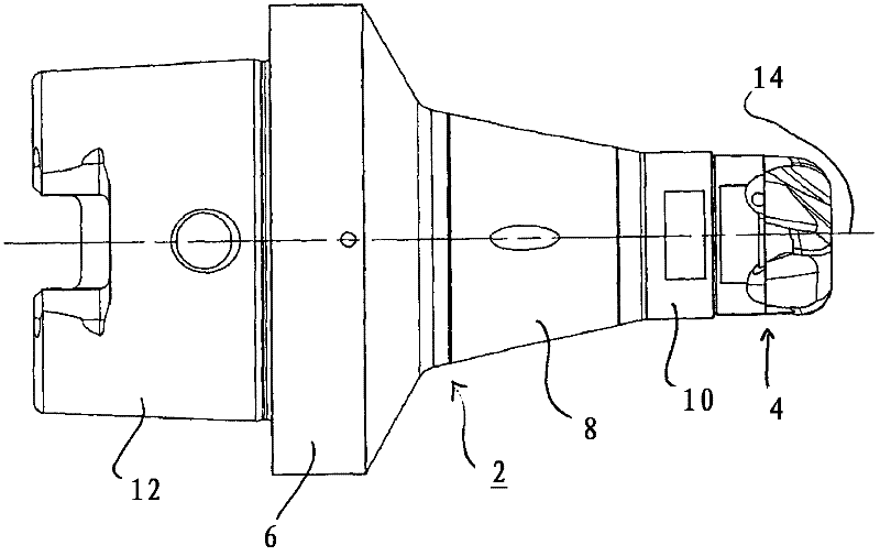
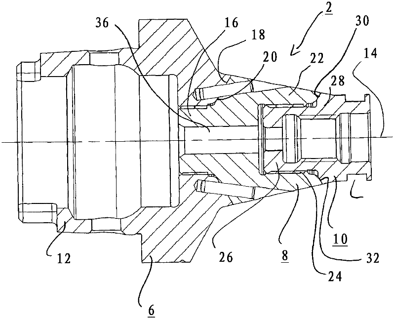
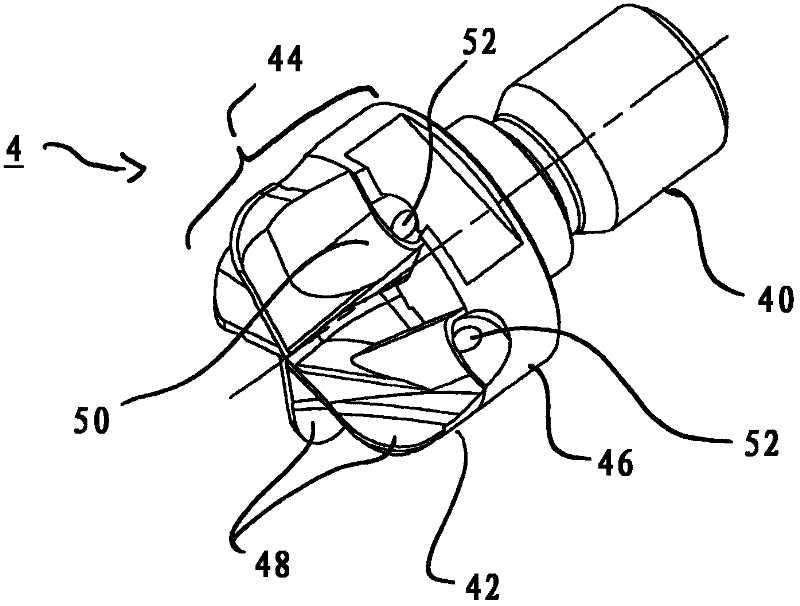
[0034] Will figure 1 and 2Tool holder 2 shown in, specifically with image 3 used in combination with special ball shank milling cutters shown in , for metal removal machining, in particular in the automotive sector for the production of ball races to enable an articulated wheel suspension. The tool holder 2 and the ball milling cutter 4 thus form a tool system, one of which is matched to the other.

[0035] The products in this case are mass-produced products and require good machining quality with short machining times. During machining, high loads occur, which can cause vibrations that lead to permanent tool wear and also lower machining quality. Tool holder 2 described hereinafter, specifically with image 3 The combination of the ball shank milling cutter 4 shown in , makes it possible to achieve high machining quality with a longer service life than the systems currently in use.

[0036] In this case the tool holder 2 is realized in three parts and has a rear machin...


PUM

PropertyMeasurementUnit
densityaaaaaaaaaa
densityaaaaaaaaaa

Abstract

The tool holder (2) is configured for fastening to a machine tool and for reversibly receiving a rotary tool (4), in particular a ball shank milling cutter. The tool holder (2) is arranged in three parts, comprising a rear machine part (6), made of a ductile elastic tool steel, that reversibly fastens to the spindle of a machine tool, and having a front clamping part (10), also made of a ductile elastic tool steel, that reversibly receives the tool (4), and having an intermediate part (8), made of a heavy metal, in particular solid hard metal, disposed between the rear machine part (6) and the front clamping part (10). Owing to the greater density of the heavy metal in comparison with the tool steel, the tool holder (2) is better able to absorb forces occurring during a milling operation, thereby achieving a milling operation that is sparing of the cutting tool, and consequently achieving a longer service life.

Description

technical field [0001] The invention relates to a tool holder having the features stated in the preamble of claim 1 and to a tool system comprising a tool holder and a tool. Background technique [0002] Such a tool holder, in particular for receiving a ball shank milling cutter, is known for example from WO 2008 / 116446 A1. Milling cutters, especially ball shank milling cutters, are often used to produce grooved races, which in the case of ball shank milling cutters are used to produce so-called ball races. A particular application is found in the field of wheel suspensions of automobiles to enable an articulated wheel fastening. In such cases the ball race is produced on a circumferential side of a cylindrical part, traversing the latter. Due to the large number of workpieces in this case, a high machining speed with high quality is sought. [0003] Particularly in the case of milling operations, in which a radially advancing movement is caused, large forces occur which ...

Claims


Application Information

Patent Timeline
Patent Type & Authority Applications(China)
IPC IPC(8): B23C5/00B23C5/26B23C5/28
CPCB23B31/11B23B2222/28B23B2222/84B23B2250/16B23C5/10B23C2210/02B23C2210/03B23C2222/28B23C2222/84B23C2250/16Y10T409/30952B23B29/022B23C5/26B23Q11/0032B23C5/20B23B29/04
Inventor U·霍博姆H·G·曼纳W·齐茨曼
Owner KENNAMETAL INC
Why Eureka
Try Eureka