Corrosion-resistant cooling structure for offshore wind turbine

A technology for wind turbines and cooling structures, applied in wind turbine components, wind turbines, wind power generation, etc., can solve problems such as increasing operating costs, hazards, and difficulty in control, and achieve a reduction in anti-corrosion levels, cost reduction, and realization of cooling effect

Active Publication Date: 2012-09-12
CSIC CHONGQING HAIZHUANG WINDPOWER EQUIP
View PDF10 Cites 9 Cited by
  • Summary
  • Abstract
  • Description
  • Claims
  • Application Information

AI Technical Summary

Problems solved by technology

On the one hand, this technology is relatively difficult to control. On the other hand, although the filter device is used to filter the air before it enters the cabin, the filter device always has a certain pore size and cannot achieve 100% filtration, so the diameter is smaller than the pore size. The particles will still enter the cabin with the air, and the corrosive media and particulate matter deposited in the cabin will increase, thus posing a threat to the rotating parts
[0007] 3. The tower wall cooling method proposed in international applications WO01 / 06121, WO2004 / 016945, and WO2010 / 069954 is to use the tower wall as a heat exchanger with the outside world to guide the air in the cabin to the tower. Heat exchange is carried out with the cold air outside through the tower wall. However, due to the limited heat dissipation area of ​​the tower wall, it is difficult to meet the requirements of high-power units. At the same time, the tower and the engine room are not sealed, and corrosive gases and particulate matter from the outside enter into the air. The cabin will pose a threat to the key equipment in it
This method effectively improves the cooling effect, but the cooling medium is expensive, and various safety valves need to be installed to prevent pipeline overpressure, which increases operating costs. At the same time, the engine room is not sealed, and the parts in the engine room are still easy to install. Hazard from external corrosive gases

Method used


Image

  • Corrosion-resistant cooling structure for offshore wind turbine
  • Corrosion-resistant cooling structure for offshore wind turbine
  • Corrosion-resistant cooling structure for offshore wind turbine

Examples


Embodiment Construction

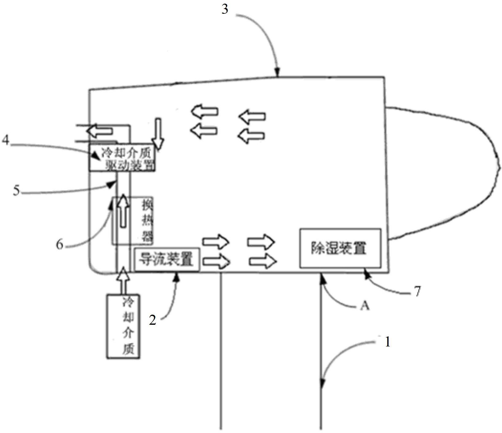
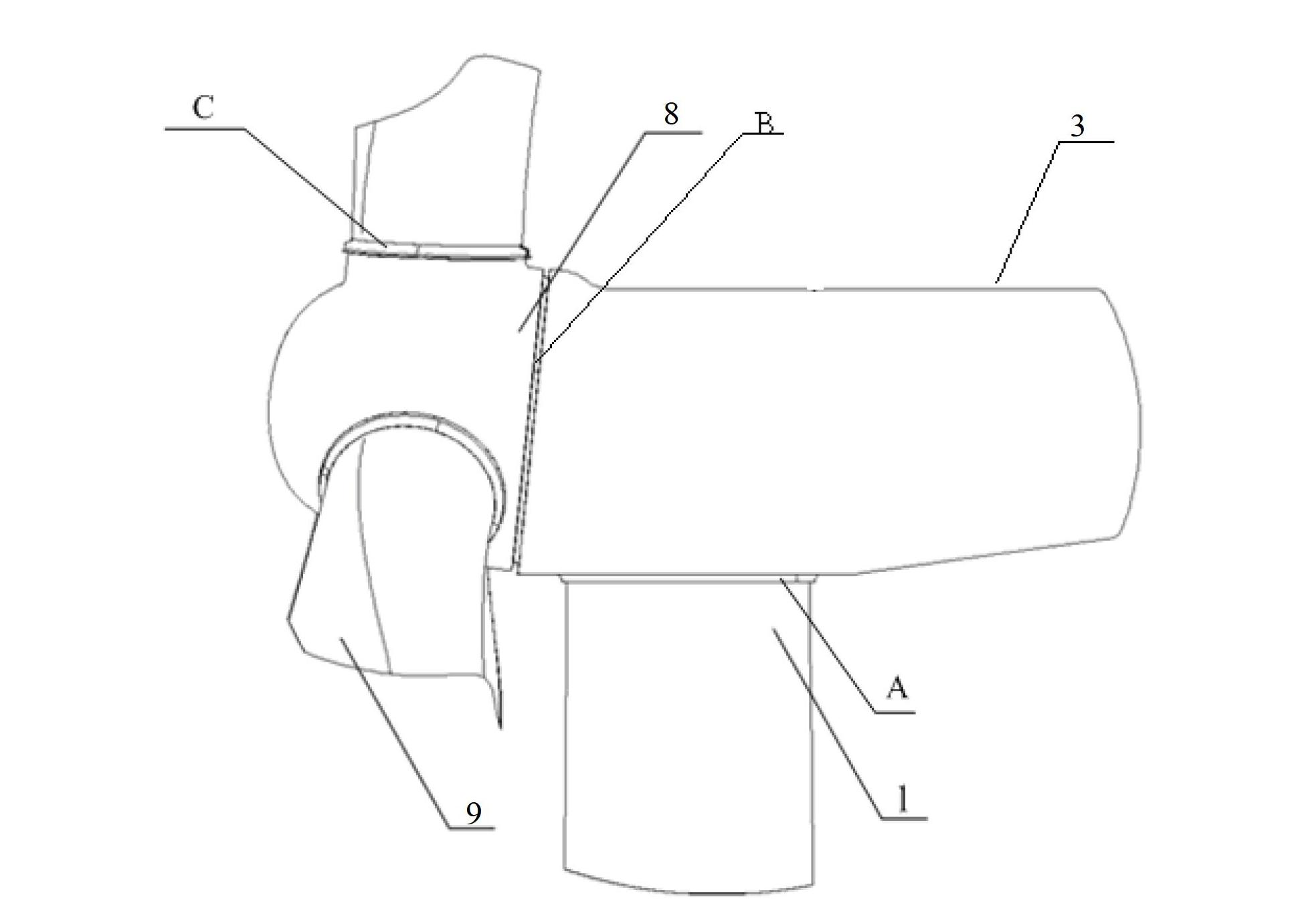
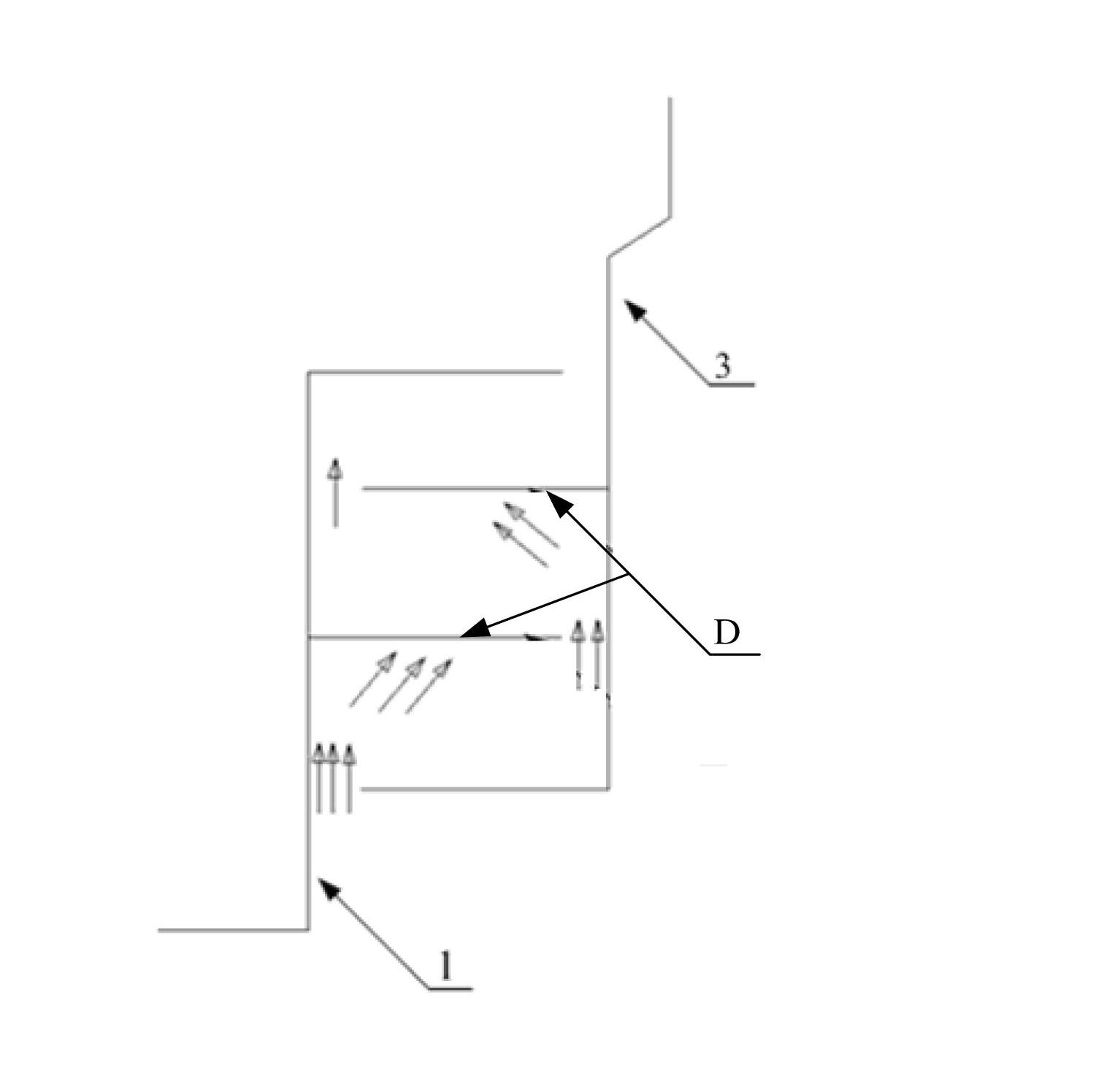
[0031] The core of the present invention is to provide an anti-corrosion cooling structure for offshore wind power generators. In the cooling structure, the matching parts of the nacelle and the tower and the mating parts of the nacelle and the main shaft are all sealed in the way of labyrinth sealing, and the airtight The air cooling system is installed in the cabin, so as to ensure that the inside of the cabin can be cooled and at the same time realize the overall sealing of the cabin, the parts inside the cabin are isolated from the outside air, and the parts inside the cabin are protected from the influence of corrosive substances in the outside air , so the corrosion resistance level of the internal parts of the engine room can be moderately reduced, and the cost of parts can be reduced.

[0032] In order to enable those skilled in the art to better understand the solution of the present invention, the present invention will be further described in detail below in conjunct...


PUM


Abstract

The invention discloses a corrosion-resistant cooling structure for an offshore wind turbine. The wind turbine comprises a tower, an engine room arranged on the tower in a rotatable mode, and a spindle arranged inside the engine room in a rotatable mode. A running fit part of the tower and the engine room and a running fit part of the spindle and the engine room are sealed in a labyrinth seal mode, and an air cooling system is arranged inside the sealed engine room. Because the rotating parts are subjected to labyrinth seal, parts inside the engine room are isolated from outside air, so that harm of corrosive substances contained in the outside air to the inside parts is reduced; and therefore, the anti-corrosion grade of the inside parts can be properly reduced, so that the cost of the parts inside the engine room is reduced; and meanwhile, an aim of cooling the interior of the engine room through the air cooling system at low operating cost is fulfilled.

Description

technical field [0001] The invention relates to the technical field of wind power generation, in particular to an anti-corrosion cooling structure of an offshore wind power generator. Background technique [0002] Marine wind turbine is a device that converts wind energy into electrical energy. It is generally composed of a tower, a nacelle and a wind wheel. The tower is generally used to support the nacelle to a high altitude. Sometimes some components, such as transformers or The converter and others are installed in the tower to facilitate maintenance and leave space for the nacelle, which contains key equipment of the wind turbine, such as gear boxes and generators. [0003] Since the rotation of the wind wheel of the marine wind turbine is transmitted to the generator rotor through the speed-increasing gear, the generator rotor rotates at high speed to generate electricity. Heat is also generated by losses and friction, convective heat transfer and heat radiation on th...

Claims


Application Information

Patent Timeline
Patent Type & Authority Applications(China)
IPC IPC(8): F03D11/00F03D80/60
CPCY02E10/72
Inventor 陈勇黄金余钟小村周祖田张万军
Owner CSIC CHONGQING HAIZHUANG WINDPOWER EQUIP
Why Eureka
Try Eureka