
Microfluidic chip with diversion body and application thereof

A technology of microfluidic chip and conducting fluid, applied in fluid controllers, laboratory containers, instruments, etc., can solve problems such as affecting test results, affecting reactions, errors, etc., to improve reaction efficiency, reduce contact time, control The effect of coating quality

Active Publication Date: 2012-09-19
BEIJING BOHUI INNOVATION TECH
View PDF7 Cites 5 Cited by
  • Summary
  • Abstract
  • Description
  • Claims
  • Application Information

AI Technical Summary

Problems solved by technology

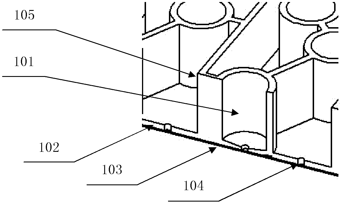
[0006] Existing polymer microfluidic chip, its container 101 such as image 3 As shown, when the solution 113 in the container is pumped out, some residual droplets 114 will remain on the inner wall of the container, which is difficult to avoid even if the inner wall of the container adopts a circular arc angle.
Residual liquid will affect the test results, it will reduce the amount of solution and cause errors; in addition, when the container is used again, other solutions will be pumped in, which will cause pollution and affect the normal reaction

Method used


Image

  • Microfluidic chip with diversion body and application thereof
  • Microfluidic chip with diversion body and application thereof
  • Microfluidic chip with diversion body and application thereof

Examples


Embodiment 1

[0046] Example 1: Preparation of coated diversion spheres

[0047] 1) Dilute the carcinoembryonic antibody used for coating 1:6000 times with 50mM sodium carbonate-sodium bicarbonate buffer solution of pH9.6, and set aside;

[0048] 2) Place a certain amount of diversion spheres in a beaker, and add the above-mentioned diluted carcinoembryonic antibody solution according to the calculation according to the amount of 100 μl per sphere;

[0049] 3) The above-mentioned beaker is sealed, placed in a 4°C environment, and coated for 20 hours;

[0050] 4) After the coating is completed, wash twice with the washing solution, calculated as 300 μl / coated sphere, and the washing solution composition is 10 mM PBS with pH 7.4 containing 5% Tween-20;

[0051] 5) After washing, place the coated ball on water-absorbing filter paper to absorb the remaining solution, then place it in a beaker, add a certain amount of blocking solution according to the amount of 150ui / coated ball, and seal at r...

Embodiment 2

[0053] Example 2: Irregular diversion body

[0054] The diversion body placed in the waste liquid pool is made of silica gel, and its shape is the same as that of the waste liquid pool, and the surface is not coated.

Embodiment 3

[0055] Example 3: Polymer microfluidic chip with flow-guiding spheres

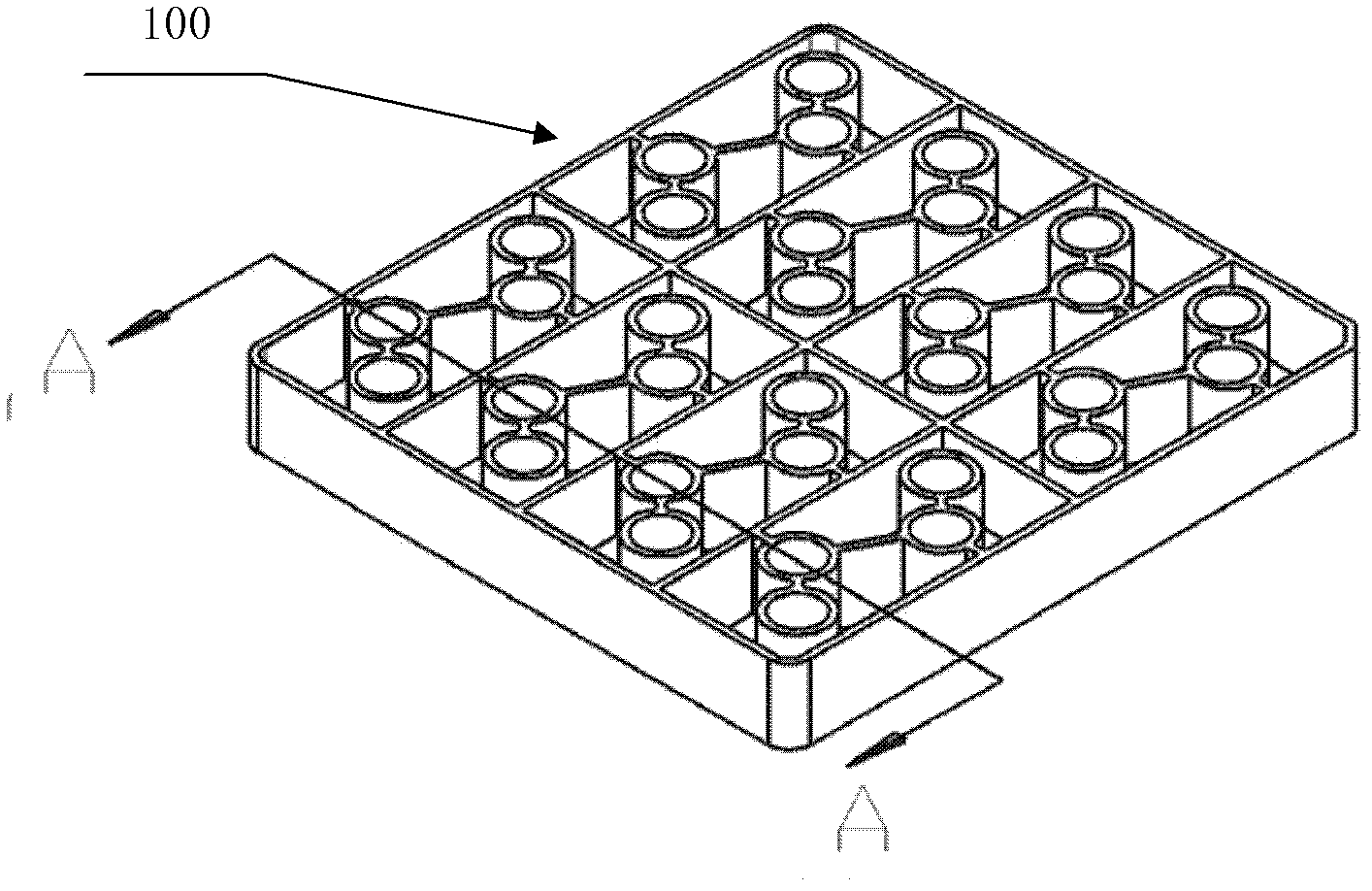
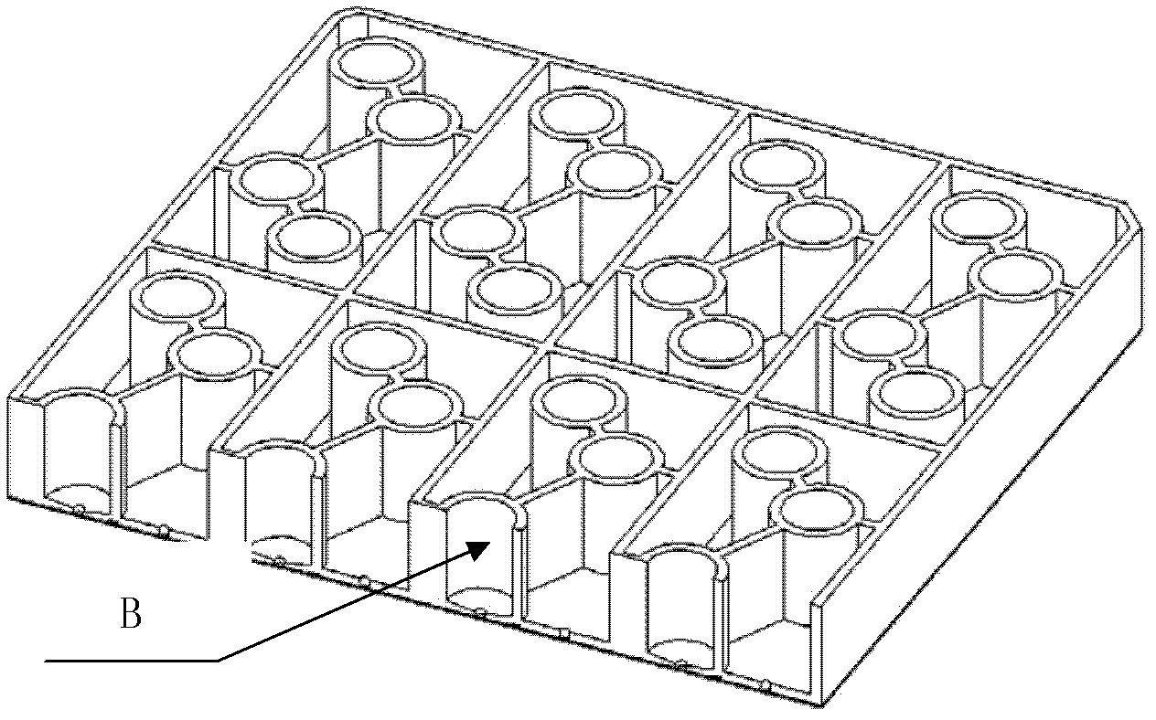
[0056] 6 solution pools, see Figure 7 : a sample pool 201, a diluent pool 202, a marker pool 203, a dissociation pool 204, a cleaning pool 205, a waste pool 206, a pool wall 105 of the solution pool, and a through hole 104 at the bottom of the pool;

[0057] 7 valves, see Figure 8 : sample pool valve 211, diluent pool valve 212, marker pool valve 213, dissociation pool valve 214, cleaning fluid valve 215, waste liquid valve 216, main valve 217, and channels 106 between the main valve and each branch valve ;

[0058] see Figure 9 , wherein, the sample pool valve 211+main valve 217+diluent pool valve 212 and the through hole 104 and the channel 106 form a bidirectional pump between the sample pool 201-the diluent pool 202, and the sample dilution pump 302;

[0059] see Figure 10 , wherein, the sample pool valve 211+main valve 217+cleaning liquid valve 21 5 and through holes, passages constitute a on...


PUM

PropertyMeasurementUnit
Diameteraaaaaaaaaa
Diameteraaaaaaaaaa

Abstract

The invention provides a microfluidic chip with a diversion body and is characterized in that the diversion body is arranged in a solution cell of the microfluidic chip, an antigen or antibody is coated on the surface of the diversion body, and the gap between the diversion body and the wall of the solution cell is 0 to 1.5 mm. The microfluidic chip can reduce drain residues and provide convenience for controlling the coating quality. The diversion body rotates in the solution cell to ensure effective contact between the antigen in the solution and the antibody coated on the surface of the diversion body, which has a more complete effect than vibration and increases the reaction efficiency.

Description

technical field [0001] The invention belongs to the field of fluid control and detection on a microscopic scale, in particular to a polymer microfluidic chip with a guiding body and an application thereof. Background technique [0002] Microfluidic technology is a technology for detecting and manipulating tiny volumes of fluids, and is a structural analysis and control method applied to biological and chemical fluid systems. Realized and potential applications of microfluidics include disease diagnosis, life science research, and biological and / or chemical sensor development. [0003] The polymeric microfluidic structure includes a substrate and a membrane. In polymeric microfluidic structures, there can be various structures on the substrate, which can be microfluidic channels or pathways, through-holes, and various containers. The substrate is combined with the diaphragm to form a valve structure, and a force is applied to deform the diaphragm, so that the valve is actua...

Claims


Application Information

Patent Timeline
IPC IPC(8): B01L3/00B01J19/00
CPCB01L3/00B01L3/502746B01L3/5025B01L2200/0647B01L2200/10B01L2300/0861B01L2300/0867B01L2400/049B01L2400/084B01L2400/086B01L2400/088G01N27/44791
Inventor 杨奇
Owner BEIJING BOHUI INNOVATION TECH
Learn More