Vacuum distillation method for improving distillate yield

A distillation method and vacuum distillation column technology, applied in the field of vacuum distillation, can solve the problems of reduced pressure drop in the oil transfer line, no plug flow, restriction, etc., to prevent cracking and coking, shorten residence time, and simple vaporization Effect

Active Publication Date: 2012-09-19
CHINA PETROLEUM & CHEM CORP +1
View PDF2 Cites 2 Cited by
  • Summary
  • Abstract
  • Description
  • Claims
  • Application Information

AI Technical Summary

Problems solved by technology

Factors affecting the temperature drop and pressure drop of the oil transfer line mainly include structural design, fluid flow pattern and flow velocity, etc. Generally, a step-by-step diameter expansion design is adopted, and the flow velocity is required to neither appear plunger flow nor exceed 90% of the critical flow velocity. Therefore, the reduction of the pressure drop in the oil transfer line is limited to a certain extent.

Method used


Image

  • Vacuum distillation method for improving distillate yield
  • Vacuum distillation method for improving distillate yield
  • Vacuum distillation method for improving distillate yield

Examples


Embodiment 1

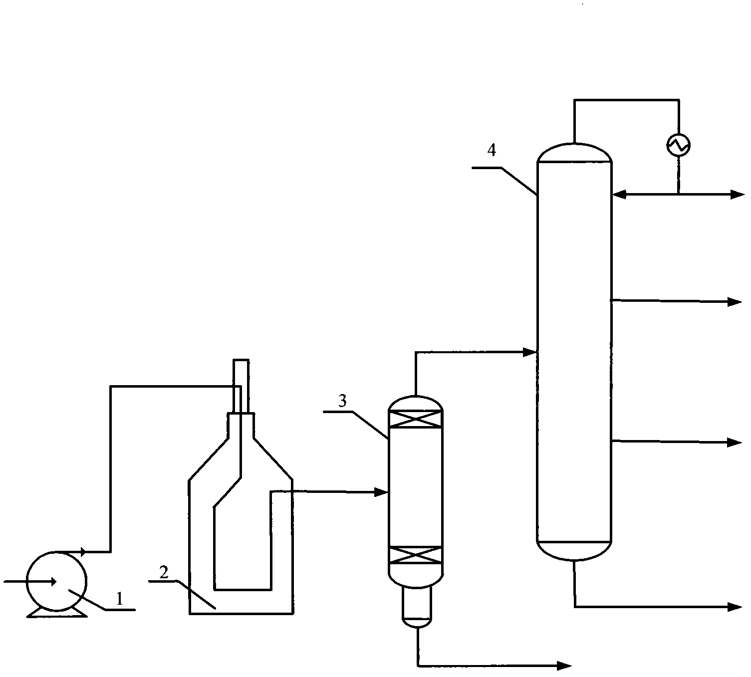
[0033] Example 1 illustrates the effect of the vacuum distillation method provided by the present invention.

[0034] Process such as figure 1 As shown, the residual oil at 350°C is pressurized by the pump 1 and then enters the decompression furnace 2. After being heated to a tower inlet temperature of 395°C, it enters the intermediate vaporization tower 3. The diameter of the vaporization tower is 1.2 of the diameter of the decompression tower. times, the bottom of the vaporization tower is 6 solid-valve trays, the opening ratio of the trays is 8%, the top of the tower is equipped with a wire mesh demister, the pressure of the vaporization tower is 8kPa, and the load of the heating furnace is 228MJ / t of raw materials. The temperature drop from the furnace outlet to the vaporization tower is 8°C. In the vaporization tower, the light component flashes into a vapor phase and enters the vacuum tower 4 to separate the vacuum distillate oil. The pressure at the top of the vacuum tow...

Embodiment 2

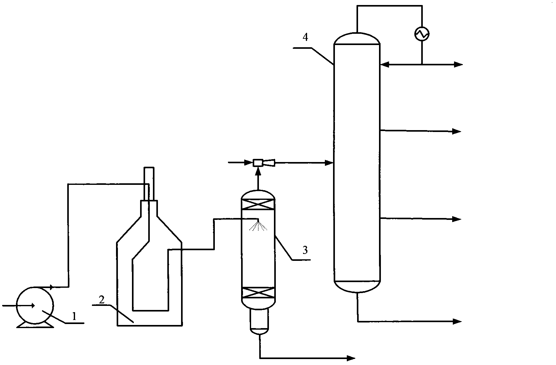
[0036] Example 2 illustrates the effect of the vacuum distillation method provided by the present invention on the vaporization process in the atomization enhanced vaporization tower.

[0037] Process such as figure 2 As shown: 350°C normal-pressure residual oil enters the decompression furnace 2 after being pressurized by the pump 1, and enters the intermediate vaporization tower 3 after being heated to a tower inlet temperature of 430°C to complete the atomization and vaporization process. The diameter of the vaporization tower is reduced 0.8 times the diameter of the pressure tower, the bottom of the vaporization tower is a high-flux grid packing, the height of the packing is 1.2m, the top of the tower is equipped with a wire mesh demister, the pressure before the entrance of the vaporization tower is 500kPa, and the load of the heating furnace is 233MJ / t raw material, the temperature drop from the outlet of the heating furnace to the vaporization tower is 4°C, and the at...


PUM

PropertyMeasurementUnit
porosityaaaaaaaaaa

Abstract

The invention relates to a vacuum distillation method for improving distillate yield. The method comprises the steps of heating atmospheric residue to a temperature of 350-460 DEG C in a vacuum furnace; introducing the atmospheric residue to a vaporizing tower, wherein the atmospheric residue is partially vaporized in the vaporizing tower; leading out the atmospheric residue at the bottom of the vaporizing tower from the device; introducing a tower top fraction in the vaporizing tower into the vacuum distillation tower, wherein a tower top pressure of the vacuum distillation tower is 0.5-5 KPa, a tower top temperature of the vacuum distillation tower is 40-100 DEG C, and a tower bottom temperature of the vacuum distillation tower is 310-360 DEG C; and fractionating through the vacuum distillation tower to obtain heavy diesel oil and vacuum gas oil. The method employs an intermediate vaporizing tower to replace a transfer line and a vaporizing stage in the conventional atmospheric/vacuum distillation processes, and provides an individual vaporization space for oil products, so that a simple vaporization of the oil products can be realized in the vaporizing tower, energy loss caused by temperature drop and pressure drop of the transfer line can be reduced, and the distillate yield of light fraction in the vacuum distillation can be improved.

Description

technical field [0001] The present invention relates to a kind of method of atmospheric and vacuum distillation of crude oil, more specifically, relate to a kind of vacuum distillation method. Background technique [0002] Atmospheric and vacuum distillation of crude oil is known as the "leader" of petroleum refining. It provides raw materials for subsequent processing units of refineries and directly provides some products. At present, the atmospheric and vacuum distillation technology mostly adopts the "two furnaces and three towers" process, namely the initial distillation tower, atmospheric furnace, atmospheric tower, vacuum furnace and vacuum tower. Improving the extraction rate of the atmospheric distillation unit can make the light components be extracted from the atmospheric tower as much as possible, and will not enter the vacuum tower again. On the one hand, more light fractions can be obtained, and on the other hand, it can reduce the pressure of the vacuum furnac...

Claims


Application Information

Patent Timeline
Patent Type & Authority Applications(China)
IPC IPC(8): C10G53/02
Inventor 袁清张占柱毛俊义秦娅黄涛
Owner CHINA PETROLEUM & CHEM CORP
Why Eureka
Try Eureka