Supercharge Your Innovation With Domain-Expert AI Agents!

Tubular object displacement identification device based on machine vision

A machine vision and identification device technology, applied in measurement devices, optical devices, instruments, etc., can solve problems such as affecting detection accuracy, small radial size, and inability to achieve, to ensure measurement accuracy, ease of use, and high resolution. The effect of measurement

Active Publication Date: 2014-06-04
江门市蒙德电气股份有限公司
View PDF6 Cites 0 Cited by
  • Summary
  • Abstract
  • Description
  • Claims
  • Application Information

AI Technical Summary

Problems solved by technology

However, due to the large aspect ratio of the above-mentioned measured object, the possibility of small radial dimensions, the possibility of axial movement and the diversity of materials, it is difficult to attach any materials and devices to the measured object, and the contact displacement method is used. The sensor needs to be in contact with the object to be measured. The general non-contact type needs to install auxiliary devices on the object to be measured, such as the reading head of the grating, the reflective device of the laser interferometer, etc., which will not only affect the detection accuracy, but even cannot be realized at all.

Method used


Image

  • Tubular object displacement identification device based on machine vision
  • Tubular object displacement identification device based on machine vision

Examples


Embodiment Construction

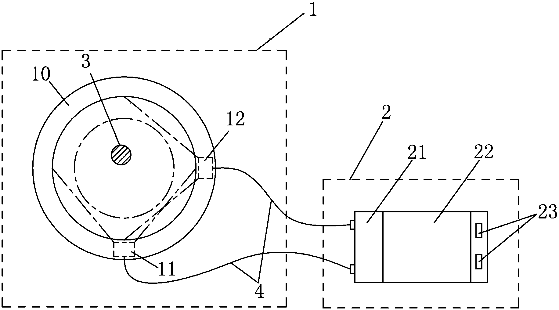
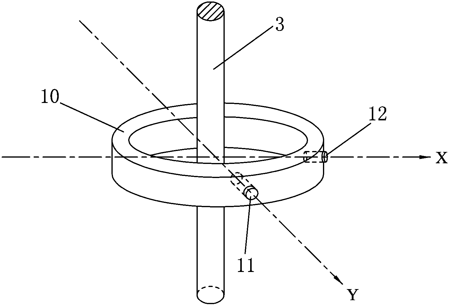
[0016] refer to figure 1 , figure 2 , a device for recognizing displacement of a tubular object based on machine vision provided by the present invention mainly includes an image acquisition device 1 and an image processing device 2 . In the image acquisition device 1, two cameras 11, 12 are fixedly mounted on the ring detector 10 perpendicular to and facing the cylindrical object 3 to be measured, and are respectively used to detect the object 3 to be measured passing through the ring detector 10 at X Axis and displacement in the Y-axis direction. In the image processing device 2, the two data lines 4 respectively input the images collected by the cameras 11 and 12 to the image acquisition card 21, and the image processing unit 22 processes the images, and describes the detection results and outputs them through the signal output port 23 .

[0017] In the described image acquisition device 1, its detector is a ring structure, and two cameras 11, 12 are fixedly installed o...


PUM


Abstract

The invention discloses a tubular object displacement identification device based on machine vision. The tubular object displacement identification device comprises an image acquisition device and an image processing device, wherein the image acquisition device comprises an annular detector; the annular detector is perpendicularly sleeved on a cylindrical object to be detected; two cameras opposite to the object to be detected are arranged on the annular detector; an angle formed between the two cameras is 90 degrees; the image processing device comprises an image acquisition card for acquiring a video signal and an image processing unit for processing an image; and the cameras are connected with the image acquisition card through a data wire. The tubular object displacement identification device based on machine vision has a simple structure and is convenient to use; and the non-contact non-interference high-speed high-resolution measurement of the translation position of the axis of the cylindrical object can be realized in a radial plane.

Description

technical field [0001] The invention relates to a machine vision-based displacement recognition device for tubular objects, specifically a non-contact detection device for detecting the translational position of the axis of a cylindrical object in its radial plane using dual CCD image sensors and image processing technology. The invention belongs to the technical field of mechanical engineering non-contact testing. Background technique [0002] In industrial automation control, a test technique for detecting the translation of the axis of a cylindrical object in its radial plane is often required, and the test technique has no limit to the length of the measured object, and the axial displacement of the measured object and speed unlimited. Its commonly used applications include: ?, finished product position correction detection of wire or pipe extrusion production line; ?, position detection when wire coiling; [0003] Displacement is a physical quantity often measured in ...

Claims


Application Information

Patent Timeline
Patent Type & Authority Patents(China)
IPC IPC(8): G01B11/02
Inventor 邓之江
Owner 江门市蒙德电气股份有限公司
Features
  • R&D
  • Intellectual Property
  • Life Sciences
  • Materials
  • Tech Scout
  • Unparalleled Data Quality
  • Higher Quality Content
  • 60% Fewer Hallucinations
Learn More