Composite-structure Fresnel lens

A technology of Fresnel lens and composite structure, which is applied in the direction of lens, condenser, optics, etc., can solve the problems of low surface hardness, lower transmittance, and high packaging cost of PMMA materials, so as to improve optical transmittance and reduce transmittance. Efficiency reduction, good wind and sand resistance effect

Inactive Publication Date: 2014-07-30
上海合瑞新能源科技有限公司
View PDF5 Cites 0 Cited by
  • Summary
  • Abstract
  • Description
  • Claims
  • Application Information

AI Technical Summary

Problems solved by technology

[0005] 1. Aspheric surface processing is difficult and costly
[0006] 2. The thickness of the lens is thick, the material cost is high, and the weight is heavy, which is not conducive to installation
[0008] 1. PMMA Fresnel lenses are mostly units, the packaging cost is high, and the packaging reliability is poor
[0009] 2. The strength of PMMA material is not high, especially not suitable for large-area Fresnel lens arrays
[0010] 3. The weather resistance of PMMA material is not good enough, and the material is prone to yellowing under long-term exposure to the sun, causing a decrease in transmittance and reducing system efficiency and life
[0011] 4. The surface hardness of PMMA material is not high, and the surface is easy to scratch in the wind and sand environment, which reduces the system efficiency and life
[0012] 4. The expansion coefficient of PMMA material is high, which is quite different from that of glass and metal, so it is difficult to seal and fix, and it is difficult to ensure the long life of the seal

Method used


Image

  • Composite-structure Fresnel lens
  • Composite-structure Fresnel lens
  • Composite-structure Fresnel lens

Examples


Embodiment Construction

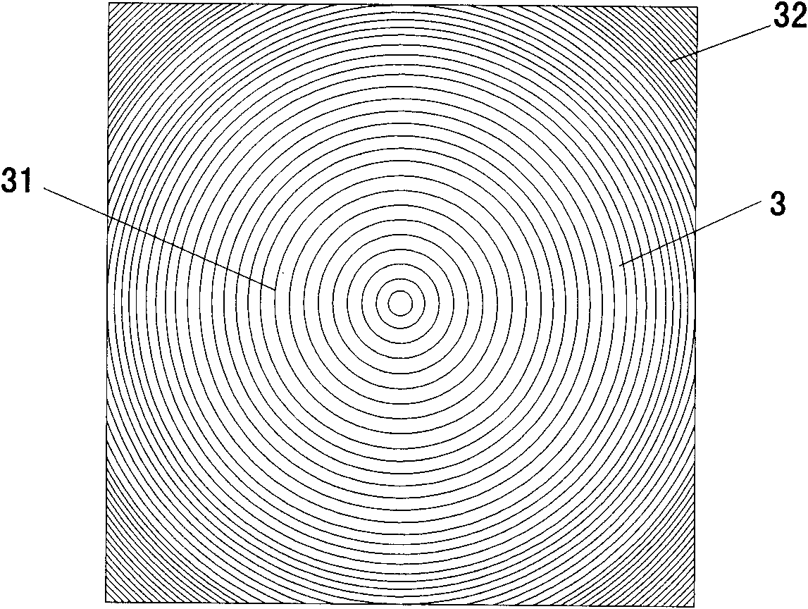
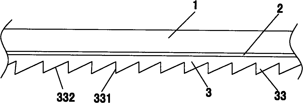
[0035] see figure 1 , figure 2 , the composite structure Fresnel lens of the present invention is formed by sequential connection of tempered flat ultra-clear glass 1, bonding layer 2 and silica gel layer 3, and the outer surface of silica gel layer 3 forms a Fresnel tooth-shaped surface, and the Fresnel tooth The shape surface is composed of a plurality of tooth-shaped concentric rings 31 or broken rings 32. The tooth-shaped cross-section of each ring is a right triangle 33, and the right angle side 331 of the right triangle is perpendicular to the upper surface of the Fresnel lens, that is, the incident surface of sunlight , the surface where the hypotenuse 332 is located forms the refraction surface of sunlight.

[0036] The toughened flat ultra-clear glass in the present invention has a thickness of 3-5 mm, and both sides are smooth surfaces; the thickness of the bonding layer is less than 0.1 mm; the thickness of the silica gel layer is not greater than 1 mm.

[0037] ...


PUM

PropertyMeasurementUnit
thicknessaaaaaaaaaa
thicknessaaaaaaaaaa
thicknessaaaaaaaaaa

Abstract

The invention relates to a composite-structure Fresnel lens which is formed by sequentially connecting tempered panel ultra-white glass, a bonding layer and a silica gel layer, wherein the outer surface of the silica gel layer forms a Fresnel tooth-form surface, the Fresnel tooth-form surface is composed of a plurality of tooth-form concentric rings or broken rings, the tooth-form section of each ring is respectively in a right-angled triangle shape, one right-angled edge of the right-angled triangle is perpendicular to the upper surface of the Fresnel lens, namely the incident plane of sunlight, and the surface where the inclined edge locates forms the refraction plane of sunlight. The inclined angle of each tooth-form refraction plane in the Fresnel tooth-form surface is increased ring by ring from the center to the outside. Compared with the prior art, the composite-structure Fresnel lens has the advantages of being high in optical transmittance, good in weather resistance, high in surface hardness, strong in sand and wind resistance, low in material cost and the like.

Description

technical field [0001] The invention relates to a solar energy concentrating device, in particular to a composite structure Fresnel lens. Background technique [0002] Human beings are facing energy shortages, the greenhouse effect is intensifying, and environmental pollution is serious. As a major clean energy source, solar energy has been paid more and more attention. The current solar power generation mainly uses monocrystalline silicon cells, polycrystalline silicon cells or thin film cells. These types of batteries are limited by the technology and principle, and the efficiency is relatively low; compared with traditional energy sources, the cost is more than doubled, which has become one of the bottlenecks restricting the large-scale application of solar power generation. [0003] High-power concentrating solar power generation technology is the third generation of photovoltaic technology. Concentrating solar energy uses GaAs cells, the photoelectric conversion effi...

Claims


Application Information

Patent Timeline
Patent Type & Authority Patents(China)
IPC IPC(8): G02B3/08G02B19/00B32B17/10
Inventor 章琳
Owner 上海合瑞新能源科技有限公司
Why Eureka
Try Eureka