Nano generator, nano generator set and self-powered system comprising nano generator or nano generator set

A technology of nanogenerators and zinc oxide nanowires, which is applied in the direction of generators/motors, nanotechnology, piezoelectric/electrostrictive/magnetostrictive devices, etc., and can solve problems such as low voltage and current, high cost, and complex structure. Problems, to achieve the effect of improving stability, improving efficiency, and strengthening contact

Inactive Publication Date: 2012-09-19
NEWNAGY TANGSHAN
View PDF1 Cites 71 Cited by
  • Summary
  • Abstract
  • Description
  • Claims
  • Application Information

AI Technical Summary

Problems solved by technology

However, the voltage and current generated by the power supply control system are

Method used


Image

  • Nano generator, nano generator set and self-powered system comprising nano generator or nano generator set
  • Nano generator, nano generator set and self-powered system comprising nano generator or nano generator set
  • Nano generator, nano generator set and self-powered system comprising nano generator or nano generator set

Examples


Embodiment Construction

[0028] Hereinafter, the present invention will be further described in conjunction with the accompanying drawings and specific embodiments,

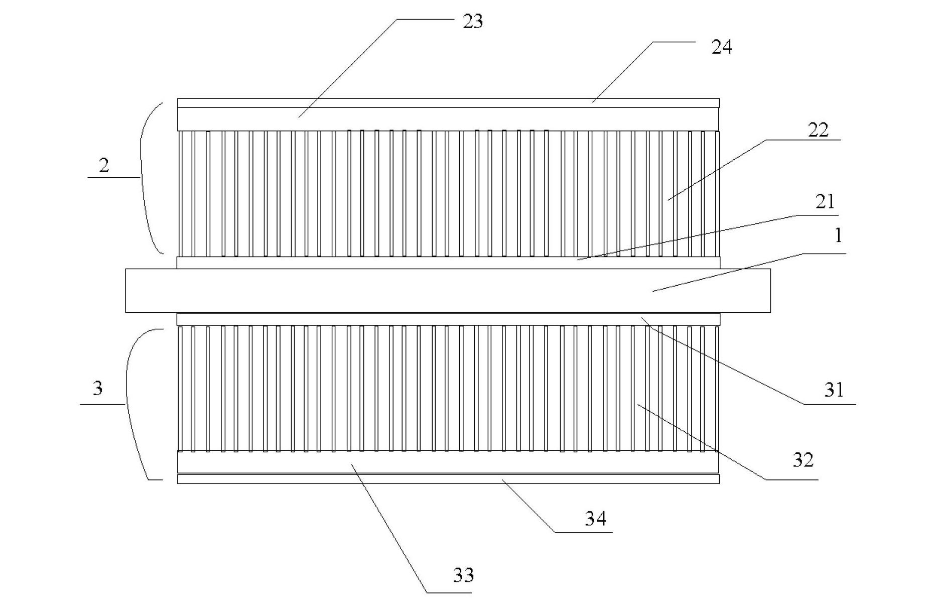
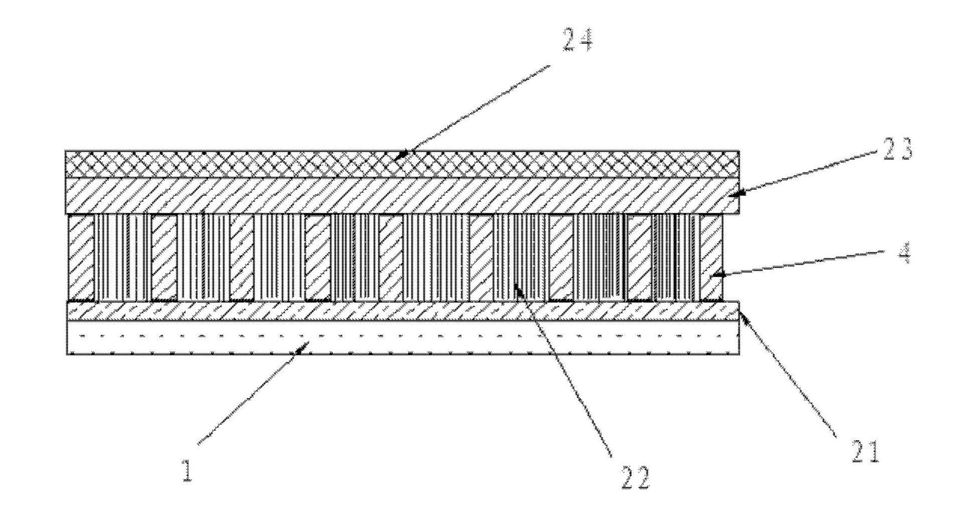
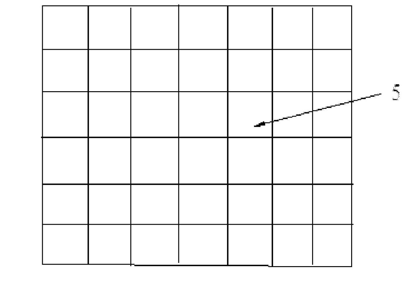
[0029] figure 1 A schematic diagram showing the composition of the nanogenerator manufacturing process according to an embodiment of the present invention. figure 2It is a schematic cross-sectional view of the upper electrode structure of the nanogenerator according to another embodiment of the present invention. image 3 It is a schematic diagram of the regional growth of zinc oxide nanowires in the present invention. Figure 4 is a schematic diagram showing the working mechanism of the piezoelectric potential generated by the nanogenerator, which represents the distribution of the piezoelectric potential in the designed structure, the transverse midline in the support substrate 1 represents the tension neutral plane, and the zinc oxide nanowires form a dense Filled solid film; if ZnO nanowires form a densely packed film with small g...


PUM


Abstract

The invention provides a nano generator, a nano generator set and a self-powered system comprising the nano generator or the nano generator set. The nano generator comprises a supporting substrate, and upper and lower electrodes which are arranged at two sides of upper and lower surfaces of the supporting substrate by glue, wherein each electrode respectively comprises a zinc oxide nanowire array layer, a macromolecular insulating layer and a conductive thin film; the zinc oxide nanowire array layers vertically grow on the supporting substrate; the macromolecular insulating layers are coated on the zinc oxide nanowire array layers; the conductive thin films are arranged on the macromolecular insulating layers; and the conductive thin films form output electrodes of voltage and current of the nano generator. The self-powered system can obtain energy from very small force in an environment through utilizing the nano generator and can store most of the energy when a sensor is at a standby mode; the collected energy is used for triggering the sensor under an active mode to rapidly process and transmit data; and therefore, the self-powered system has huge potentials of application on the aspects of radio biological sensing, environment/infrastructure monitoring, sensor networks, individual electronic products, even national security.

Description

technical field [0001] The invention relates to a nanogenerator, a nanogenerator set and a self-power supply system thereof, in particular to a self-power supply system used for long-distance data transmission and driven by a wireless independent operating nanogenerator. Background technique [0002] At present, the power supply system uses hydroelectric power generation, thermal power generation, etc., and a power supply control system is installed to control their use. However, the current large-area nano-power supply system composed of nano-generators has not proposed a remote and automatic power supply control system, resulting in low efficiency of the nano-power supply system, which cannot be automatically and remotely controlled. Emerging developments in cash nanotechnology have shifted from inventing individual components to integrated systems capable of performing one or more designed functions by integrating a set of nanocomponents with modern microelectronics. A g...

Claims


Application Information

Patent Timeline
IPC IPC(8): H01L41/04H01L41/113B82Y40/00
CPCH01L41/082H01L41/04H01L41/113H01L41/1134H02N2/186H02N2/18H10N30/306
Inventor 王中林胡又凡张岩许晨
Owner NEWNAGY TANGSHAN
Why Eureka
Try Eureka