Reversing shifting conveyer device and conveyer system

A conveying device and conveying system technology, applied in the direction of conveyor objects, transportation and packaging, etc., can solve the problems of single conveying direction, limited production efficiency, waste of production space, etc., achieve high production efficiency and ensure accurate monitoring.

Active Publication Date: 2012-09-26
NANTONG MINGXING TECH DEV CO LTD +1
View PDF5 Cites 12 Cited by
  • Summary
  • Abstract
  • Description
  • Claims
  • Application Information

AI Technical Summary

Problems solved by technology

When there are materials that need to be transferred from the conveying unit in the X conveying direction to the conveying unit in the Y conveying direction, and at the same time, other materials need to pass through the intersection node and be conveyed along the X conveying direction, it is necessary to set an additional fan-shaped conveyor belt on the intersection node. The reversing conveyor belt cannot meet the conveying requirements of these two different directions at the same time
In addition, the reversing conveyor belt requires a large turning radius and space, which makes the circulating line take the shape of a hollow runway, and the hollow

Method used


Image

  • Reversing shifting conveyer device and conveyer system
  • Reversing shifting conveyer device and conveyer system
  • Reversing shifting conveyer device and conveyer system

Examples


Embodiment 1

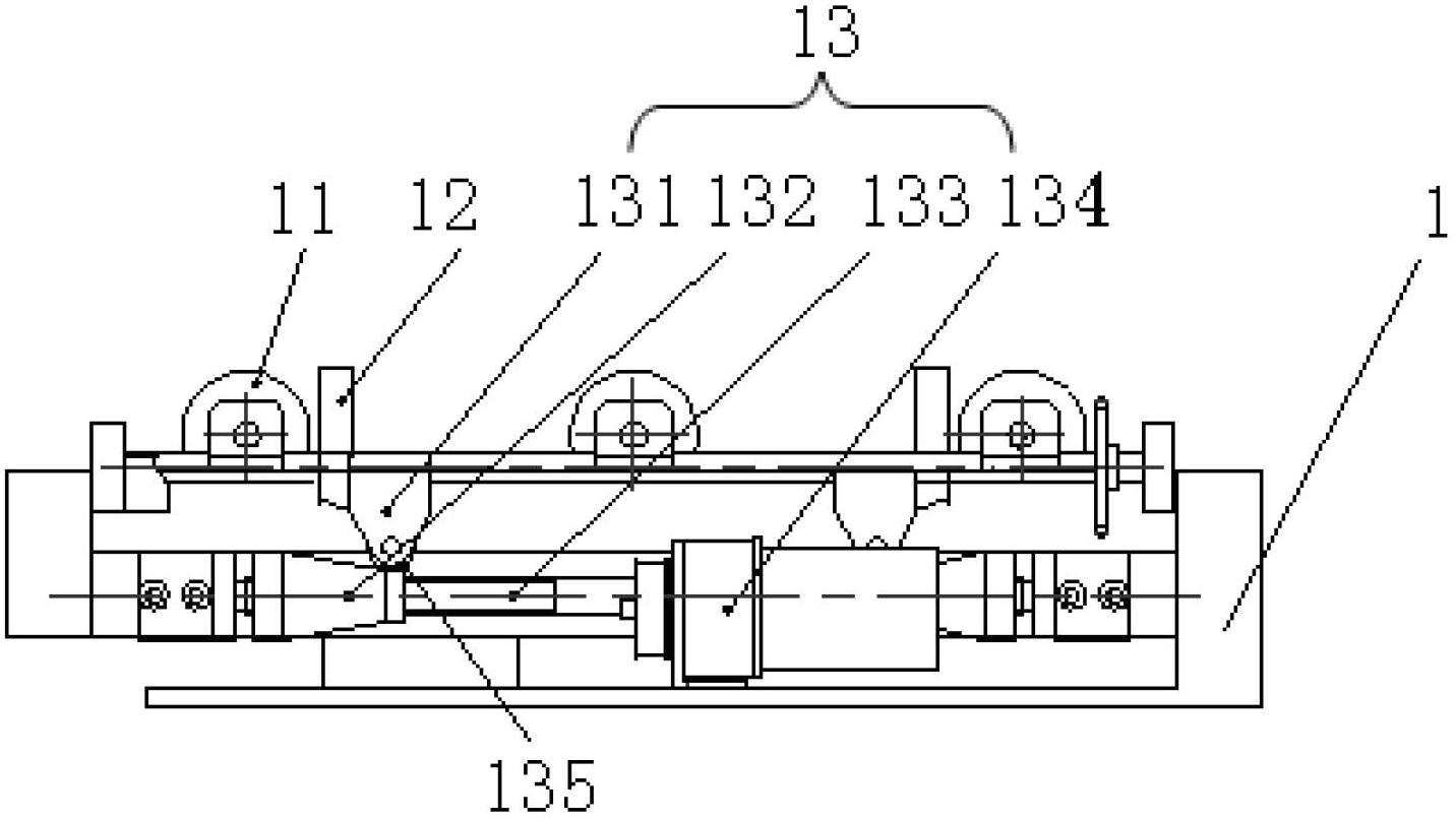
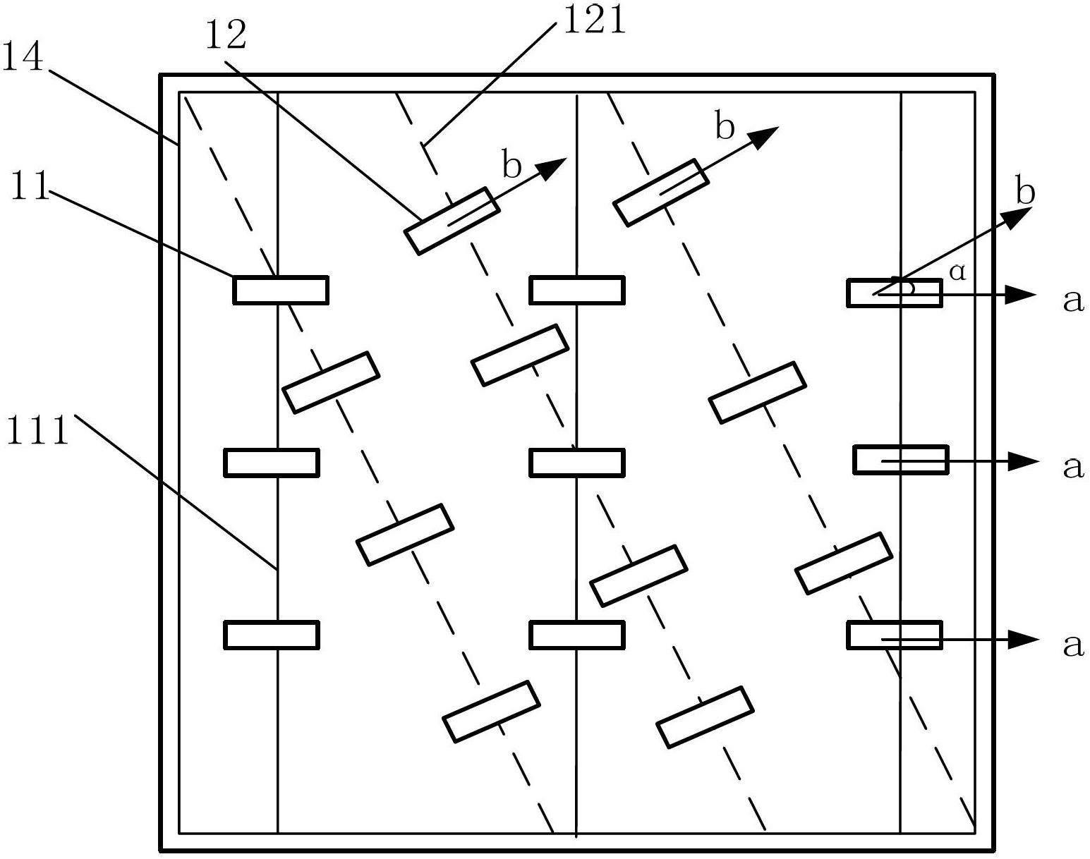
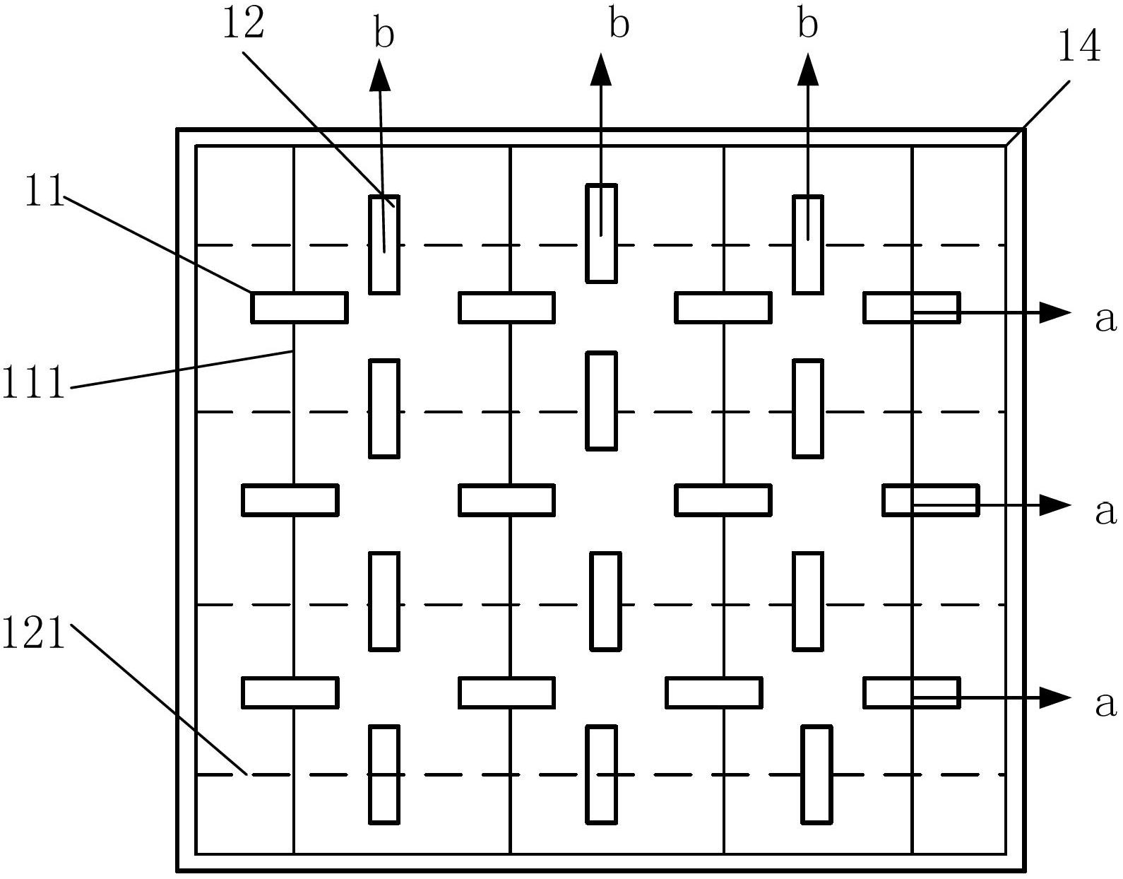
[0057] Example 1 as figure 1 , figure 2 As shown, the function of the reversing transfer conveying device 1 is to realize the reversing reloading and co-direction conveying of materials. The so-called reversing reloading is to change the original movement direction of materials, and the so-called same-direction conveying is to maintain the original movement of materials. direction. It includes multiple sets of fixed roller sets, multiple sets of reversing roller sets, a switching mechanism 13 and a frame 14, wherein each set of fixed roller sets includes a plurality of fixed roller sets 11, and the first conveying surface A is determined by the highest point of each fixed roller 11, The rolling direction of the fixed rollers 11 is the conveying direction a of the first conveying surface A; each set of reversing rollers includes a plurality of reversing rollers 12, and the second conveying surface B is determined by the highest point of each reversing roller 12, and the rever...

Embodiment 2

[0063] Embodiment 2, with respect to embodiment 1, both the first conveying surface A and the second conveying surface B can rise or fall relative to the frame 14, when the conveying direction of the material needs to be changed, then change the relative height of the two conveying surfaces, Realize the reversing transfer of materials from one conveying surface to the other; when the conveying direction of the material does not need to be changed, the relative height of the two conveying surfaces remains unchanged, and the material is conveyed along the conveying direction of the conveying surface.

Embodiment 3

[0064] Example 3 as Figure 5 As shown, the difference from Embodiment 1 or 2 is that each reversing roller 12 is driven by a reversing motor 122, so that each reversing roller 12 can realize a three-dimensional movement, that is, along a direction perpendicular to the center of the reversing roller. The diameter R of the shaft is for shaft rotation and vertical lift. Each reversing motor 122 runs synchronously, and the conveying direction b of the second conveying plane B formed by the highest point of the reversing roller 12 also changes thereupon. The angle α between the conveying directions b also changes accordingly.


PUM


Abstract

The invention relates to reversing shifting conveyer device and a conveyer system. The reversing shifting conveyer device comprises a first conveying surface for conveying materials in the same direction and a second conveying surface for shifting materials in the reversing direction; an included angle is formed between the conveying direction of the first conveying surface and the conveying direction of the second conveying surface; the first conveying surface is higher than the second conveying surface when the materials are conveyed in the same direction; and the second conveying surface is higher than the first conveying surface when the materials are shifted in the reversing direction. Because the included angle is formed between the conveying direction of the first conveying surface and the conveying direction of the second conveying surface, the first conveying surface and the second conveying surface cannot be switched on height, so that the materials from an upstream conveying unit enters a downstream conveying unit through the first conveying surface when the materials are conveyed in the same direction; the materials from the upstream conveying unit passes through the second conveying surface and directly enters the conveying unit in the other direction when the materials are shifted in the reversing direction. The actions of the reversing shifting can be realized through the switching of the height of the two conveying surfaces without the sector turning radius and occupation of floor spaces, so that the conveyer system with higher complexity can be established in the unit area.

Description

technical field [0001] The invention relates to a material conveying device, in particular to a reversing transfer conveying device and a conveying system. Background technique [0002] The assembly line is one of the important components of the modernization of discrete manufacturing. The traditional conveying unit is a working plane that can realize linear and one-way conveying of objects on it. The conveying unit has the advantages of large conveying capacity, simple structure, convenient maintenance, and standardized components. It is widely used in mining, metallurgy, coal, clothing manufacturing, electronic devices, and food processing industries to convey discrete materials or finished items. According to the requirements of the conveying process, the conveying unit can be conveyed by a single unit, or multiple units can be formed into a conveying system with various shapes and multiple nodes to meet the operation needs of different layout types. The length and assem...

Claims


Application Information

Patent Timeline
IPC IPC(8): B65G47/52
Inventor 王宏安钟康俞明王健何伟
Owner NANTONG MINGXING TECH DEV CO LTD
Why Eureka
Try Eureka