

Packaging method
A method of encapsulation and a technology of encapsulation wires, which are applied in glass molding, glass manufacturing equipment, electrical components, etc., and can solve the problems that glass wires cannot obtain yield, etc.
- Summary
- Abstract
- Description
- Claims
- Application Information
AI Technical Summary
Problems solved by technology
Method used
Image

Examples
Embodiment 1
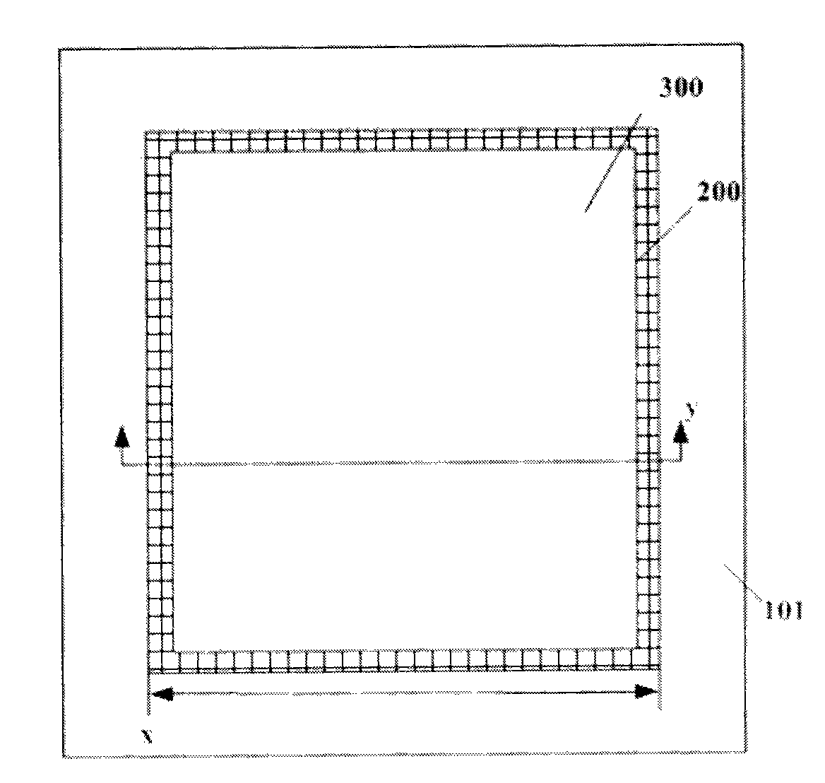
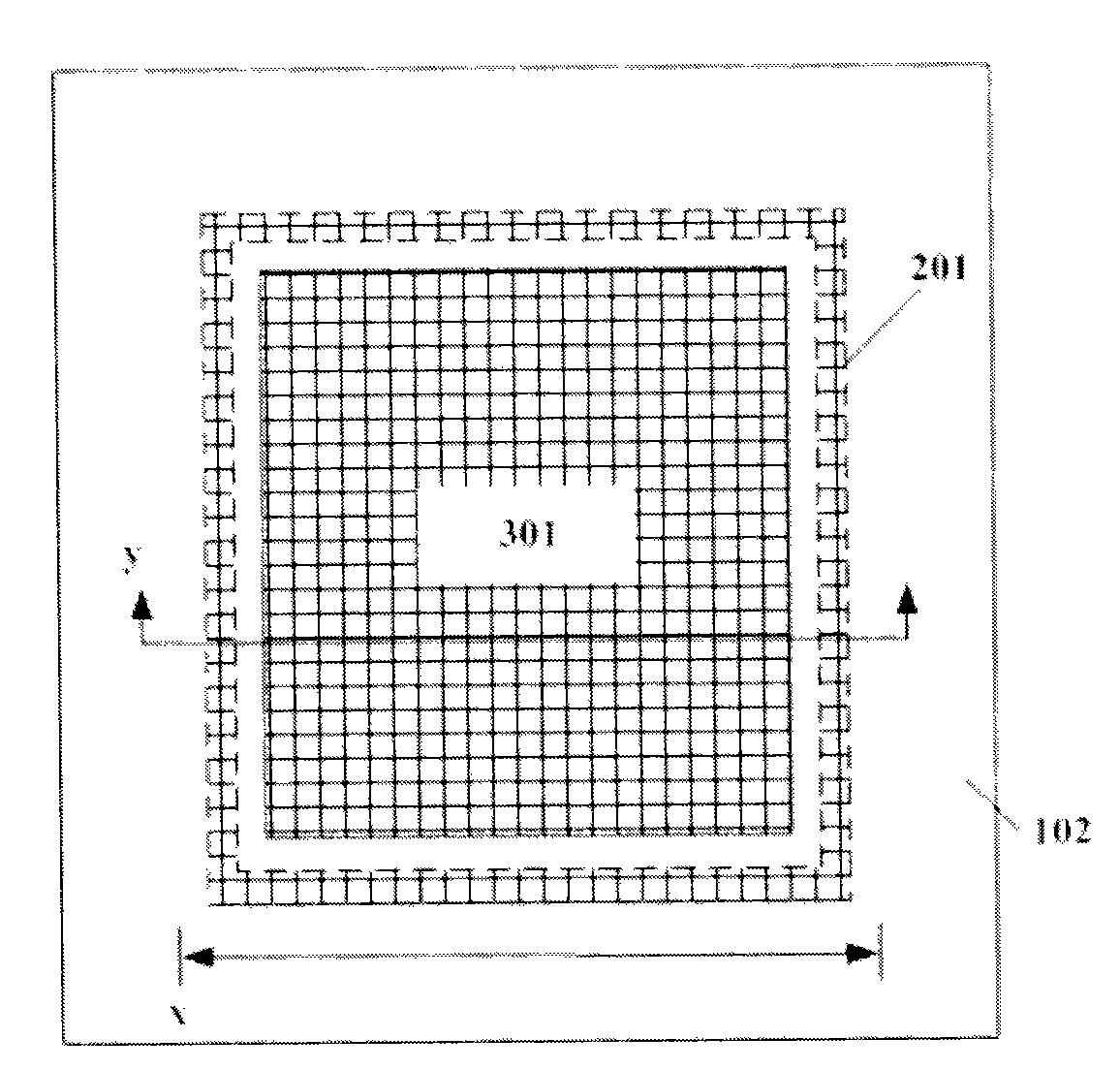
[0049] refer to EAGLE XG TM Display Grade Glass Substrates Product Information, you can know that the thickness change (Thickness Range, 150mm Moving Window) index of this type of glass is less than 20um, the average thickness change to 1mm is about 0.13um, the width of the packaging line is generally 1mm, and the length is currently usually Less than 20mm (diagonal line of small and medium-sized OLED screens <7″, the division ratio is generally 0.618, and the long side direction is about 11mm). The surface thickness variation of the glass substrate is much smaller than the thickness variation of the currently used packaging glass frit sintered body, so the influence of the thickness variation of the glass substrate on the laser welding gap effect is much smaller than the thickness variation of the glass frit sintered body. If Using the formula in US20090069164, the maximum thickness change is also between 3um~7um; if the formula in US20090069164 is not used, the maximum th...
Embodiment 2
[0076] This embodiment introduces a kind of fine powder 404, preferably the diameter is less than 2um, and its main component can be SiO 2 Or metal oxide or other materials with high absorption of laser radiation and electrical insulation; the powder can also be SiO 2 Or a mixture of two or more metal oxides or other materials with high absorption of laser radiation and electrical insulation; the powder can also be SiO 2 Or a mixture of two or more metal oxides or other materials with high absorption of laser radiation and electrical insulation and fine metal powder; in particular, when directly mixed with ordinary glass powder and made into a paste, the powder is actually It can be only fine metal powder; the powder can be particles with different particle sizes or particles with relatively uniform particle size, preferably particles with uniform particle size.
[0077] For use with SiO 2 Or other fine filling powder 404 of glass crystal composition particles, due to SiO 2...
Embodiment 3
[0096] This embodiment introduces a fine powder 404, preferably with a diameter less than 2um, and its main component can be SiO 2 Or metal oxide or other materials with high absorption of laser radiation and electrical insulation; the powder can also be SiO 2 Or a mixture of two or more metal oxides or other materials with high absorption of laser radiation and electrical insulation; the powder can also be SiO 2 Or a mixture of two or more metal oxides or other materials with high absorption of laser radiation and electrical insulation and fine metal powder; in particular, when directly mixed with ordinary glass powder and made into a paste, the powder is actually It can be only fine metal powder; the powder can be particles with different particle sizes or particles with relatively uniform particle size, preferably particles with uniform particle size.
[0097] For use with SiO 2 Or other fine powder 404 of glass crystal composition particles, due to SiO 2 Or the CTE (Coe...
PUM
| Property | Measurement | Unit |
|---|---|---|
| Size | aaaaa | aaaaa |
Abstract
Description
Claims
Application Information