
Starting-generating device for miniature turbojet engine or turbocharger

A jet engine and turbocharger technology, applied in the field of starter power generation devices, can solve the problems of affecting turbojet combustion efficiency, requiring large power supply capacity, hindering air inhalation, etc., and achieving simple and reliable structure, long endurance, and reduced weight. Effect

Active Publication Date: 2012-09-26
BEIJING LIANGMING TONGCHUANG WATER TREATMENT EQUIP DEV CENT
View PDF6 Cites 8 Cited by
  • Summary
  • Abstract
  • Description
  • Claims
  • Application Information

AI Technical Summary

Problems solved by technology

[0002] At present, the starting of the micro turbojet mainly adopts a special brush starter motor, which includes a permanent magnet rotor, a stator, a stator coil, a shaft and a bearing, etc., and is usually installed in front of the turbojet, but there are following problems in use: The current is large, the power supply capacity is large, and it is only used during the starting process. After the engine is started, the starter motor will no longer work, and because it is installed in front of the engine impeller, it hinders the intake of air and affects the turbojet combustion efficiency. In addition, the current A turbocharger with an engine uses the exhaust gas discharged from the engine as power to drive the turbine to drive the impeller to press air into the engine to achieve the purpose of improving the combustion efficiency of the engine, but it only starts to work after the engine starts, and before the engine starts The turbocharger has no power and cannot play the role of compressing air. The turbocharger does not work during the engine start process, especially when the diesel engine starts at low temperature, it cannot help the start process; moreover, the current hybrid Cars don't yet have self-charging devices that use engine exhaust to generate electricity

Method used


Image

  • Starting-generating device for miniature turbojet engine or turbocharger
  • Starting-generating device for miniature turbojet engine or turbocharger
  • Starting-generating device for miniature turbojet engine or turbocharger

Examples


Embodiment Construction

[0016] Below, the present invention will be further described in conjunction with the accompanying drawings and specific embodiments.

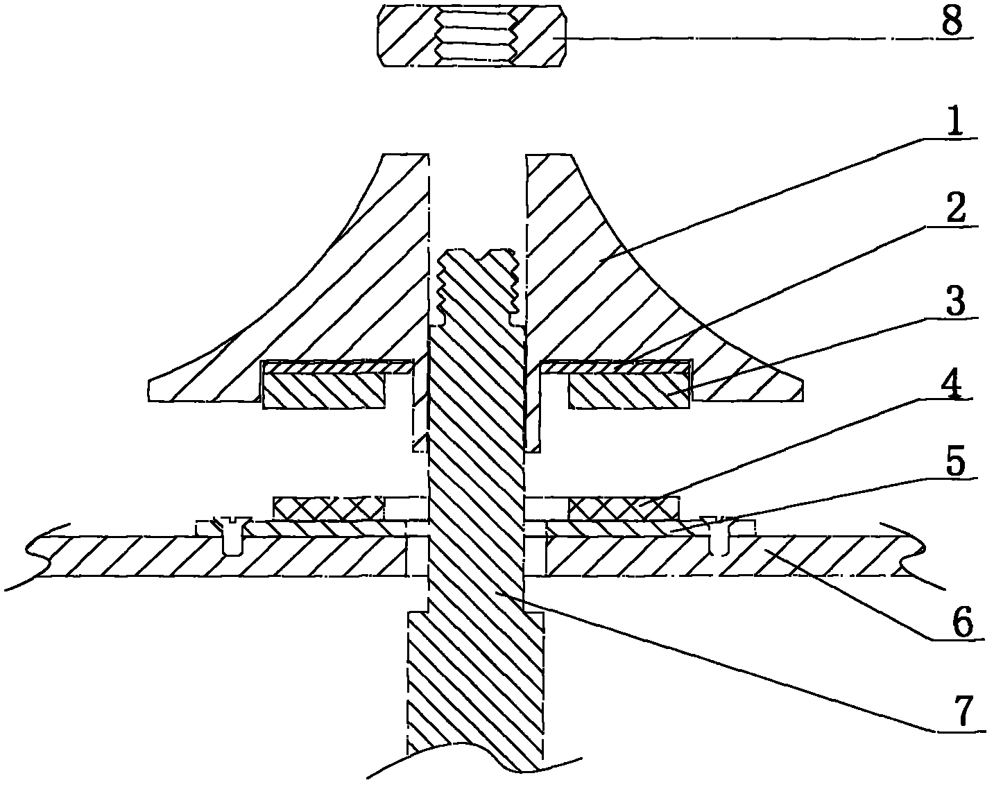
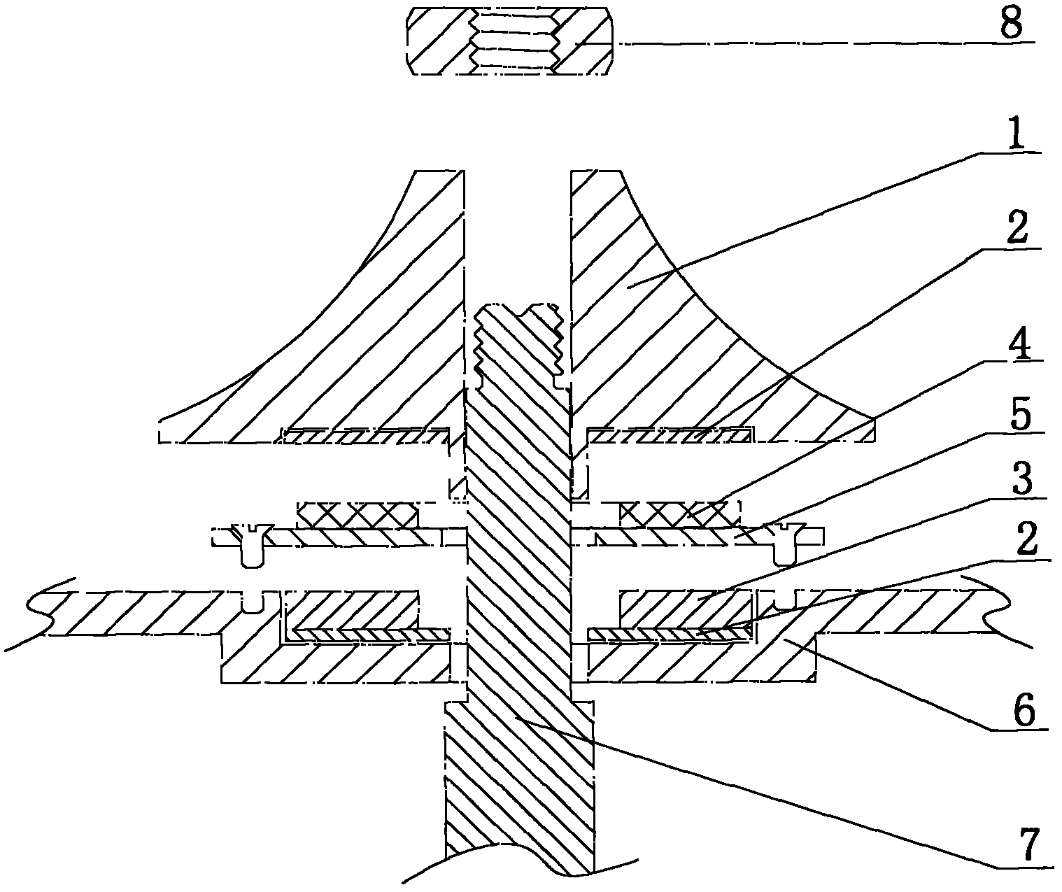
[0017] In the implementation of the present invention, as attached figure 1 As shown, the permanent magnet rotor and stator coil of the motor are installed on the inner side of the impeller 1 on the micro turbojet engine or turbocharger, and the permanent magnet rotor 3 and the magnetizer 2 are fixed on the inner side of the impeller 1 at the same time, and can also be placed on the inner side of the impeller 1 Open a groove suitable for the shape of the permanent magnet rotor 3, then place the permanent magnet rotor 3 and the magnetizer 2 in the groove and embed the impeller 1 to fix it; fix the disc stator coil 4 on the stator mounting base plate 5, and then place the The stator mounting base plate 5 is fixed on the rear cover plate 6 of the diffuser or turbocharger compressor of the turbojet engine, the disk stator coil 4 corresponds to the...


PUM


Abstract

The invention relates to a starting-generating device, particularly relates to a starting-generating device for a miniature turbojet engine or a turbocharger and aims at providing a device which is simple in structure, improves energy efficiency and integrates starting and generating. An adopted technical scheme is as follows: a permanent magnet rotor and a stator coil are arranged at the inner side of an impeller of the miniature turbojet engine or the turbocharger, wherein the impeller rotates along with a rotating shaft; the permanent magnet rotor rotates along with the rotating shaft; the stator coil is fixed a diffuser of the miniature turbojet engine or a compressor rear cover of the turbocharger; and the permanent magnet rotor, the stator coil, the impeller and the rotating shaft are arranged coaxially. The starting-generating device is unlikely to be damaged due to the hidden installation position; the rotating shaft of an original machine is utilized and a rotor bearing is omitted, therefore the structure is simple and reliable; and the starting-generating device integrates two functions of starting and generating, therefore resources are saved and the energy efficiency is improved.

Description

technical field [0001] The invention relates to a start-up generating device, in particular to a start-up generating device for a micro turbojet engine or a turbocharger of an engine. Background technique [0002] At present, the starting of the micro turbojet mainly adopts a special brush starter motor, which includes a permanent magnet rotor, a stator, a stator coil, a shaft and a bearing, etc., and is usually installed in front of the turbojet, but there are following problems in use: The current is large, the power supply capacity is large, and it is only used during the starting process. After the engine is started, the starter motor will no longer work, and because it is installed in front of the engine impeller, it hinders the intake of air and affects the turbojet combustion efficiency. In addition, the current A turbocharger with an engine uses the exhaust gas discharged from the engine as power to drive the turbine to drive the impeller to press air into the engine...

Claims


Application Information

Patent Timeline
IPC IPC(8): F01D19/00
CPCY02T50/671F02C6/12F01D15/10F05D2260/85H02K7/14H02K21/24F02C7/275F05D2250/82Y02T50/60
Inventor 佟宪良
Owner BEIJING LIANGMING TONGCHUANG WATER TREATMENT EQUIP DEV CENT
Learn More