Recovery system with heat accumulator for internal combustion engine exhausting waste heat and control method

A technology of exhaust waste heat and recovery system, which is applied in the direction of internal combustion piston engine, coolant flow control, exhaust device, etc., and can solve the problem that the dynamic working process lasts for a long time, cannot realize practical application, cannot make full use of internal combustion engine, etc. problem, to achieve the effect of small output power fluctuation, high useful work output, and extended life

Inactive Publication Date: 2012-09-26
中投亿星新能源投资有限公司
View PDF9 Cites 26 Cited by
  • Summary
  • Abstract
  • Description
  • Claims
  • Application Information

AI Technical Summary

Problems solved by technology

Using waste heat for heating can make good use of the waste heat of the engine in winter, but it cannot make full use of the waste heat of the internal combustion engine when heating is not needed in other seasons
The use of temperature difference power generation technology is limited by low conversion efficiency, and it is still not possible to realize practical applications.
Refrigeration devices using adsorption heat pumps are often too bulky, inefficient, and not suitable for automotive internal combustion engine applications
The waste heat recove

Method used


Image

  • Recovery system with heat accumulator for internal combustion engine exhausting waste heat and control method
  • Recovery system with heat accumulator for internal combustion engine exhausting waste heat and control method
  • Recovery system with heat accumulator for internal combustion engine exhausting waste heat and control method

Examples


Embodiment Construction

[0033] The present invention will be further described in detail below in conjunction with the accompanying drawings.

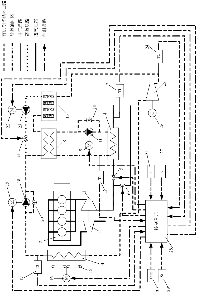
[0034] The exhaust waste heat recovery system of internal combustion engine with heat accumulator of the present invention, its connection diagram is as follows figure 1 As shown, including heat transfer oil circuit, organic Rankine cycle circuit, heat storage circuit and control circuit. The heat transfer oil circuit for absorbing exhaust heat of internal combustion engine includes the following components: working medium pump 11, regulating motor 9, pressure regulating valve 10, exhaust heat exchanger 4, evaporator 8, exhaust normally open switch valve 5, Exhaust normally closed on-off valve 6 and the pipeline connecting them. The components included in the organic Rankine cycle circuit for waste heat heat work conversion of internal combustion engines include: working fluid pump 18, regulating motor 19, pressure regulating valve 20, evaporator 8, heat acc...


PUM


Abstract

The invention provides a recovery system with heat accumulator for internal combustion engine exhausting waste heat and a ontrol method. The internal combustion engine exhausting waste heat is transmitted to organic fluid in an organic rankine cycle by utilizing a conduction oil circuit, and evaporation of the organic fluid is realized; heat from the organic fluid is absorbed or released by utilizing the heat accumulator in series with the organic rankine cycle; enthalpy change in expansion process is converted into useful work output by utilizing an expander; organic fluid flow is adjusted in a small scope according to rotating speed and load of the internal combustion engine; closed loop control of the fluid flow in the heat accumulator circuit is realized according to an overheating temperature of the organic fluid in the outlet of the heat accumulator; closed loop control of the heat conduction oil flow is realized with tail gas temperature in the outlet of the exhaust pipe as feedback; and closed loop control of a fan motor is realized with the organic fluid temperature in the outlet of a condenser as feedback. The waste heat recovery system can fully utilize the engine exhausting waste heat and guaranties that flow change of the organic fluid is not significant when the exhausting waste heat changes in a large scope in a dynamic working process of the engine, thus a small output-power fluctuation amplitude of the expander is guarantied.

Description

technical field [0001] The invention belongs to the technical field of waste heat recovery, and relates to an internal combustion engine exhaust waste heat recovery system with a heat accumulator and a control method. The system uses the heat transfer oil circuit to transfer the waste heat in the exhaust gas of the internal combustion engine to the working fluid in the evaporator of the organic Rankine cycle, and uses the heat accumulator connected in series in the organic Rankine cycle to absorb or release heat from the organic working fluid For the organic working fluid, the single-screw expander is used to output useful work to drive the generator to generate electricity, and the designed closed-loop control system adjusts the thermal cycle working status of the heat transfer oil circuit, the organic Rankine cycle circuit and the heat storage circuit according to the working status of the internal combustion engine. Background technique [0002] At present, only a small p...

Claims


Application Information

Patent Timeline
IPC IPC(8): F01N5/02F01C13/00F01C20/24F01P7/04
CPCY02T10/16Y02T10/12
Inventor 张红光王恩华范伯元杨凯
Owner 中投亿星新能源投资有限公司
Why Eureka
Try Eureka