Wastewater ammonia nitrogen blow-off treatment reaction device

A technology of ammonia nitrogen blow-off and reaction device, which is applied in the direction of degassed water/sewage treatment, etc., can solve the problems of affecting the blow-off effect, excessive gas and liquid, channel flow and wall flow, etc., so as to prevent the phenomenon of channel wall flow and improve stability The effect of avoiding waste of gas and liquid

Active Publication Date: 2013-10-16
JIANGSU YIHUAN GROUP
View PDF3 Cites 0 Cited by
  • Summary
  • Abstract
  • Description
  • Claims
  • Application Information

AI Technical Summary

Problems solved by technology

Ammonia distillation has a better deamination effect, but it requires higher equipment requirements and higher investment and operation costs; while stripping and stripping methods have lower requirements for processing equipment, and are conventional packed towers or plate separation equipment , for example, Chinese patent CN201110363900.9 discloses a kind of ammonia nitrogen stripping and absorbing integrated tower, which is characterized in that a gas-water separator is arranged on the upper part of the tower body, and an absorption cloth is arranged in turn on the lower part of the gas-water separator. Water tank, umbrella-shaped waterproof cover, sewage water distributor, first filling area, second filling area, the return pipe is set on one side of the umbrella-shaped waterproof cover, and the fan interface is set on the lower side of the second filling area. Above, the water outlet is set on the lower side of the tower body, which still adopts the packing method to achieve the purpose of gas-water mixing. When the waste water flows through the packing layer, it cannot fully mix with the gas, and more gas-liquid is required, and it is easy to The phenomenon of ditch wall flow is generated, which affects the blow-off effect; and for example, Chinese patent ZL200720006185.2 discloses an ammonia nitrogen blow-off device, which is provided with a circular cylinder, and a water inlet pipe and a suspension ring are arranged on the upper part of the circular cylinder. There is an exhaust port on the top of the cylinder, a diffuser head, a sieve plate, a support block and a manhole at the outlet of the water inlet pipe, the inlet of the diffuser head is connected to the water inlet pipe, and an air inlet pipe, support The feet and the water outlet pipe are provided with an upper ceramic Pall ring and a lower ceramic Pall ring in the inner cavity of the circular cylinder, an upper support beam is provided under the upper ceramic Pall ring, and an upper ceramic Pall ring is provided between the upper ceramic Pall ring and the support beam. With ceiling and support blocks
A lower support beam is provided under the lower ceramic Pall ring, and a lower flower plate and a support block are provided between the lower ceramic Pall ring and the lower support beam. Through the ceramic Pall ring equivalent to the filler in the inner cavity of the circular cylinder, thereby To achieve the purpose of gas-liquid mixing, the required gas-liquid is still more, the serious wall flow phenomenon in the ditch leads to high energy consumption, and the removal effect is unstable, which needs to be improved
[0004] Chinese patent CN1600693A high-efficiency deamination tower, aiming at the characteristics of the ammonia nitrogen stripping agent, designed the ammonia nitrogen stripping tower with one of bubble cap, float valve, sieve plate, tongue shape and grid plate as the tray. Although this kind of equipment The total gas-liquid ratio is reduced, but there will be channel flow and wall flow phenomenon, which needs to be improved

Method used


Image

  • Wastewater ammonia nitrogen blow-off treatment reaction device
  • Wastewater ammonia nitrogen blow-off treatment reaction device
  • Wastewater ammonia nitrogen blow-off treatment reaction device

Examples


Embodiment 1

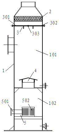
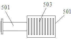
[0021] Embodiment 1: as figure 1 , figure 2 The shown wastewater ammonia nitrogen blow-off treatment reaction device includes a shell 1, and the shell 1 is sequentially arranged with a gas-water separation layer 2, a water distribution device 3, an umbrella-shaped waterproof cover 4, and an air distribution device. 5. The umbrella-shaped waterproof cover 4 divides the shell 1 into upper and lower chambers (101, 102). The upper chamber 101 is provided with a drain pipe 6 on the bottom shell 1. The water distribution device 3 is composed of a water inlet pipe 301 and an air inlet pipe. 302, two-fluid nozzle 303, the water inlet pipe 301 is connected with the air inlet pipe 302, and the two-fluid nozzle 303 facing downward is arranged at the connection to form a three-way structure, the three-way structure is straight tubular, and the two sides are respectively The water pipe 301, the air inlet pipe 302, and the two-fluid nozzle 303 are arranged at the junction of the water inl...

Embodiment 2

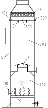
[0022] Embodiment 2: With reference to Embodiment 1, a kind of waste water ammonia nitrogen blow-off treatment reaction device, described air distribution device 5 is arranged on the air inlet pipe 501 on the side wall of the lower chamber 102 shell, and is arranged right against the air inlet pipe 501 Composed of several evenly arranged sheet-like spiral cylinders 504, the number of sheet-like spiral cylinders is 24-32 pieces / m 2 .

[0023] The ammonia nitrogen stripping treatment reaction device for wastewater of the present invention can adopt single-stage or multi-stage serial arrangement.


PUM


Abstract

The invention discloses a wastewater ammonia nitrogen blow-off treatment reaction device which comprises a shell, wherein a gas water separation layer, a water distribution device, an umbrella-shaped water shield and a gas distribution device are distributed in the shell at intervals from top to bottom in sequence; the shell is divided into an upper chamber and a lower chamber by the umbrella-shaped water shield; a drain pipe is arranged on the shell at the bottom of the upper chamber; the water distribution device consists of a water inlet pipe, a gas inlet pipe and a double-fluid spray nozzle, wherein the water inlet pipe and the gas inlet pipe are communicated; and the communication part of the water inlet pipe and the gas inlet pipe is provided with the downward double-fluid spray nozzle to form a three-way structure, so that gas-liquid waste caused by mixing gas and liquid by utilizing a packing layer can be effectively avoided, channeling and wall flow phenomena can be effectively prevented, and the stability of ammonia nitrogen blow-off treatment is improved.

Description

technical field [0001] The invention relates to waste water treatment equipment in the field of environmental protection, in particular to a waste water ammonia nitrogen stripping treatment reaction device. Background technique [0002] With the vigorous development of petrochemical, pharmaceutical, pesticide and fine chemical industries, a large amount of high-concentration ammonia nitrogen wastewater is produced in the process of chemical production. If such wastewater is discharged directly without treatment, it will cause great damage to the water environment. [0003] At present, the treatment methods for high-concentration industrial ammonia-nitrogen wastewater mainly include: stripping method, steam stripping method, ammonia distillation method, and chemical precipitation method. Among them, the chemical precipitation method has not yet been applied in large-scale engineering due to its high operating cost and complicated operation; the three methods of air stripping,...

Claims


Application Information

Patent Timeline
Patent Type & Authority Patents(China)
IPC IPC(8): C02F1/20
Inventor 张如云杭鑫王新锋胡青张宇
Owner JIANGSU YIHUAN GROUP
Why Eureka
Try Eureka