Near-infrared laser scanning confocal imaging system

A laser scanning and imaging system technology, applied in the optical field, can solve the problems of difficult to observe tissue, difficult to meet multi-dimensional, deep-level observation, inconvenient operation, etc.

Active Publication Date: 2012-10-03
SUZHOU INST OF NANO TECH & NANO BIONICS CHINESE ACEDEMY OF SCI
View PDF5 Cites 55 Cited by
  • Summary
  • Abstract
  • Description
  • Claims
  • Application Information

AI Technical Summary

Problems solved by technology

However, although the two-photon laser fluorescence imaging technology uses a near-infrared light source, it can realize the observation of thick biological samples, but because the emission wavelength of the fluorescent dyes used is still in the visible range, there are still absorption and scattering problems in biological tissues. , making it difficult to observe deeper tissue
[0004] Moreover, the existing laser scanning confocal microscopy system and two-photon excitation fluorescence microscopy system generally have problems such as complex structure, inconvenient operation, slow imaging speed, and low image resolution, especially difficult to meet the requirements of biological tissues and other similar samples. The need for multi-dimensional and in-depth observation

Method used


Image

  • Near-infrared laser scanning confocal imaging system
  • Near-infrared laser scanning confocal imaging system
  • Near-infrared laser scanning confocal imaging system

Examples


Embodiment 1

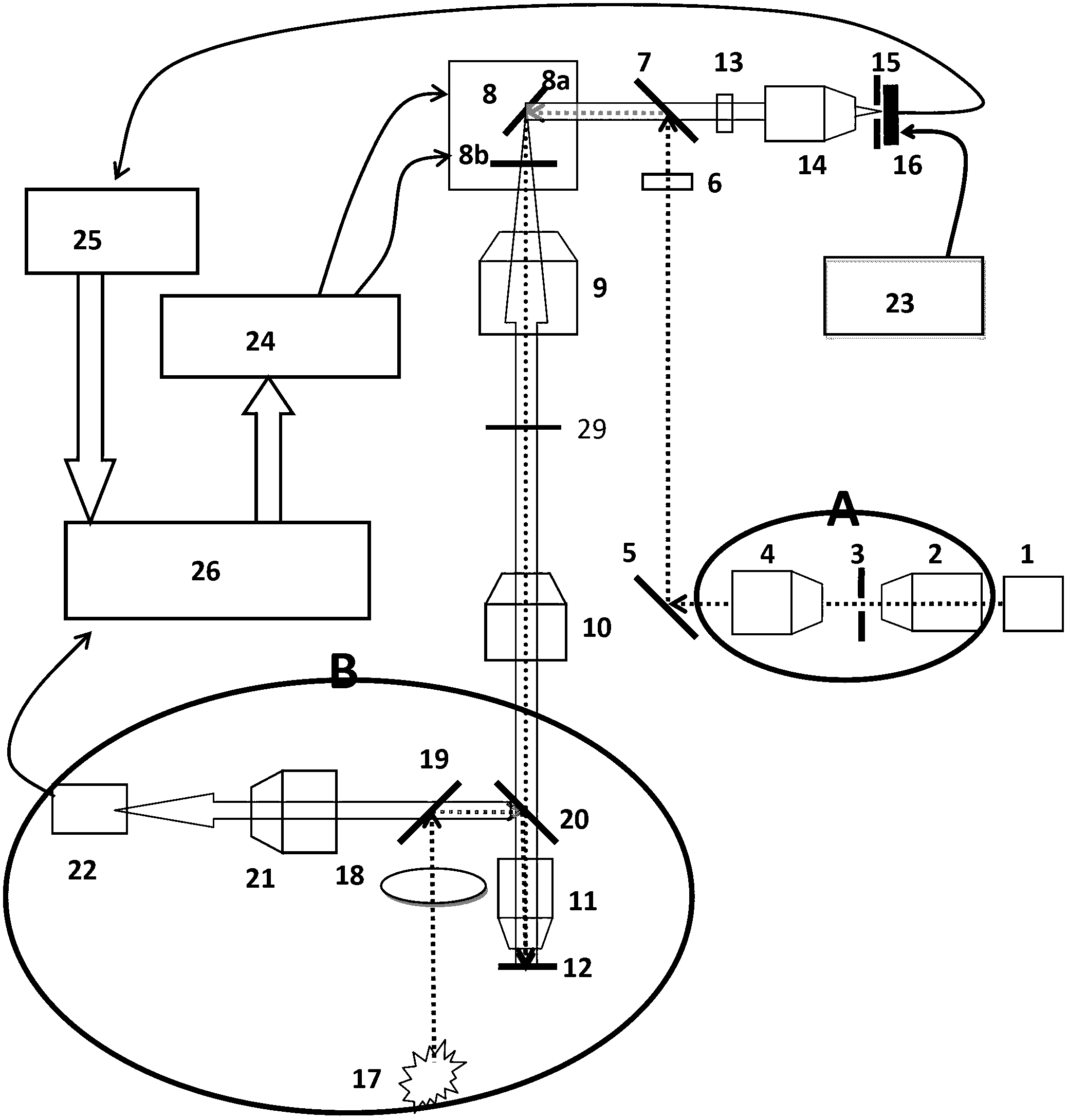
[0064] refer to figure 2 , the main structure of this embodiment is the same as figure 1 It is similar, but the Kohler illumination system B is added. The function of the Koehler illumination system is to assist the near-infrared laser scanning confocal imaging system to find the focal plane position of the imaging objective lens, that is, to place the biological sample on the infrared laser scanning confocal imaging system through the Kohler illumination system. Focus position of the imaging system.

[0065] The Koehler illumination system B is composed of a white light source 17 , an imaging lens 18 , a half mirror 19 , a mirror 20 , an imaging objective lens 11 , a barrel lens 21 and a CCD 22 . The white light source 17 is imaged by the imaging lens 18, and reflected by the half-reflective mirror 19 and the reflector 20, the image of the white light source is reflected to the rear focus position of the imaging objective lens 11, so that uniform illumination is formed on t...

Embodiment 2

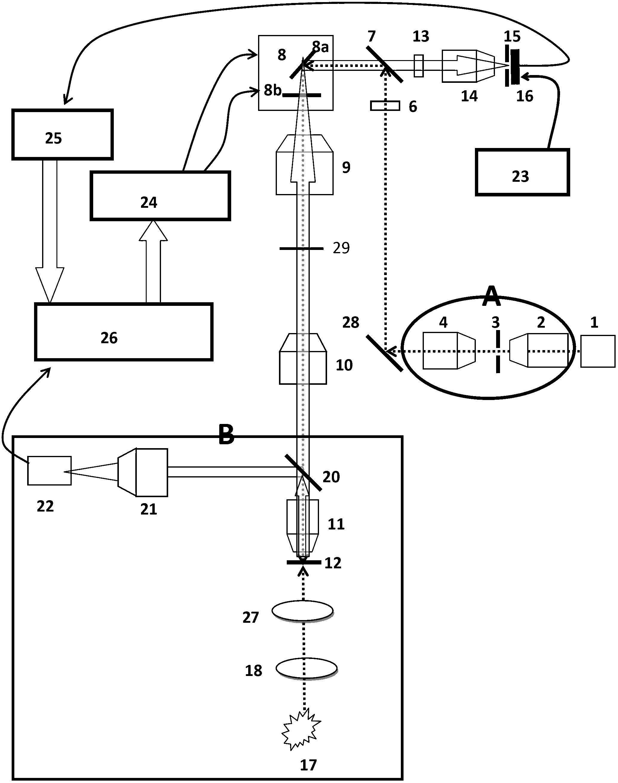
[0070] refer to image 3 , the working principle of this embodiment is similar to that of Embodiment 1, the only difference is that the Kohler lighting method adopts transmissive lighting, and its specific implementation process is as follows:

[0071] The white light source 17 forms an image at the focal point of the lens 27 through the lens 18, and the light emitted by the white light source image becomes parallel light through the lens 27, and uniformly illuminates the biological sample 12 from below the biological sample. The light emitted by the sample is formed by the imaging objective lens 11, reflected by the mirror 20, and finally imaged by the lens tube lens 21 on the CCD22.

[0072] After the position of the biological sample is determined by the Kohler illumination system, the reflector 20 is moved away from the optical path between the lens tube lens 10 and the imaging objective lens 11, and the white light source is turned off at the same time. Then, near-infrar...

Embodiment 3

[0075] refer to Figure 4, this embodiment adopts the transmissive Kohler illumination method as in Embodiment 2, and the difference is that the detection light path of the Kohler illumination system is modified. The specific implementation process is:

[0076] The biological sample 12 is uniformly illuminated from below the biological sample using the white light illumination optical path in Embodiment 2, and the embodiment 1 (see figure 2 ) and Example 2 (see image 3 The filter 6 in ) is placed between the reflector 5 and the collimating lens 4, and the reflector 5 is replaced by a half-reflective mirror 28, and the reflector 20 is removed. Place the tube lens 21 and CCD22 into the Figure 4 location shown. In this way, the Koehler illumination biological imaging detection optical path and the laser excitation biological fluorescence detection optical path share the imaging objective lens 11 , lens tube lens 10 , f-theta lens 9 and scanning galvanometer 8 .

[0077] A...


PUM

PropertyMeasurementUnit
wavelengthaaaaaaaaaa
reflectanceaaaaaaaaaa

Abstract

The invention discloses a near-infrared laser scanning confocal imaging system, which comprises a light path scanning unit and a control unit which adopt a confocal structure, wherein the light path scanning unit comprises a near-infrared laser source, a collimation and extension module, a laser optical filter, a dichroic reflector, a scanning galvanometer, an f-theta lens, a tube lens, an imaging objective lens, a fluorescent optical filter, a convergent lens, a pinhole, a detector and the like, the control unit comprises a motion control module used for controlling the scanning galvanometer, a data acquisition module used for acquiring an output signal of the detector, a data processing module connected with the motion control module and the data acquisition module, and the like. The method matched with the system is characterized in that a sample is marked with near-infrared quantum dots with the fluorescence emission spectrums between 932nm and 1250nm, and then the sample is detected by the near-infrared laser scanning confocal imaging system. According to the system disclosed by the invention, deep-level imaging of samples such as biological tissues can be accurately and efficiently realized, and the system has a simple structure and is easy to operate.

Description

technical field [0001] The invention relates to a confocal microscope system and its application, in particular to a laser scanning confocal imaging system with a working wavelength range in the near-infrared band, and the application of the system to biological tissues and other tiny devices marked with near-infrared quantum dots A method for imaging and observing structures belongs to the field of optical technology. Background technique [0002] As an indispensable technical means in the field of biomedicine, bioluminescence imaging technology has been widely used, and it is a powerful tool for observing cell morphology, structure and life phenomena. At present, the widely used biological fluorescence imaging technology is the laser scanning confocal microscope developed in the 1980s. It is characterized by the use of pinhole technology to eliminate the interference of light signals outside the focus on the image, thereby greatly improving the clarity and clarity of the i...

Claims


Application Information

Patent Timeline
Patent Type & Authority Applications(China)
IPC IPC(8): G01N21/64
Inventor 李敏王懋吴东岷翟晓敏
Owner SUZHOU INST OF NANO TECH & NANO BIONICS CHINESE ACEDEMY OF SCI
Why Eureka
Try Eureka