Bipolar electromagnetic scanning micro lens

A scanning micromirror, bipolar technology, applied in television, piezoelectric/electrostrictive/magnetostrictive devices, piezoelectric effect/electrostrictive or magnetostrictive motors, etc., can solve the long response time of devices , deal with complex circuits, limited application range and other issues, to achieve the effect of improving the work response time, low process complexity, and increasing the scanning range

Inactive Publication Date: 2012-10-03
CHONGQING UNIV
View PDF5 Cites 13 Cited by
  • Summary
  • Abstract
  • Description
  • Claims
  • Application Information

AI Technical Summary

Problems solved by technology

The traditional electromagnetic MOEMS scanning micromirror generally only has a unipolar drive, which causes the device to have disadvantages such as large volume, small rotation angle, poor stability, high power consumption, and short life.
Most of the electromagnetic MOEMS micromirrors that have been widely studied are driven by unipolar (attractive or repulsive force), which results in a very limited maximum deflection angle displacement of the micromirror under the condition of a certain magnetic field and current. The characteristics of the structure severely limit the wide application of electromagnetic micromirrors in the field of MOEMS, resulting in the emergence of very few mature MOEMS commercial devices that use electromagnetic drives.
If this kind of unipolar drive structure is to achieve a large deflection displacement or deflection angle, it is necessary to increase the magnetic field strength and increase the drive current, or reduce the stiffness of the beam, which will inevitably increase the system volume while improving the system drive. voltage, which severely limits its range of application
On the other hand, reducing the strength of the beam will significantly reduce the mechanical strength of the micromirror, resulting in a decrease in linearity during work and being vulnerable to impact damage
In addition, this kind of unipolar drive structure has a long response time of the device itself, so the operating frequency can only be used in a lower frequency environment, which is not suitable for applications with higher frequencies.
In addition, most of the MOEMS scanning micromirrors in the early stage need to add an additional set of external measurement system to measure their rotation angle. The whole system is bulky and the subsequent processing circuit is complicated.
These limit the application of scanning micromirrors in MOEMS

Method used


Image

  • Bipolar electromagnetic scanning micro lens
  • Bipolar electromagnetic scanning micro lens
  • Bipolar electromagnetic scanning micro lens

Examples


Embodiment Construction

[0030] Hereinafter, preferred embodiments of the present invention will be described in detail with reference to the accompanying drawings. It should be understood that the preferred embodiments are only for illustrating the present invention, but not for limiting the protection scope of the present invention.

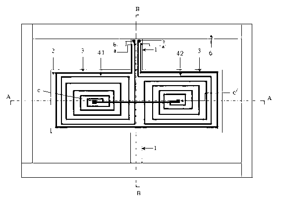
[0031] 1-torsion beam; 2-micro-mirror; 3-angle sensor; 41-micro-driver I; 42-micro-driver II; 6-support frame; a-angle sensor electrode I; a'-angle sensor electrode II; b- Drive electrode I; b'-drive motor II; c-connect electrode I; c'-connect electrode II.

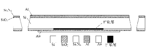
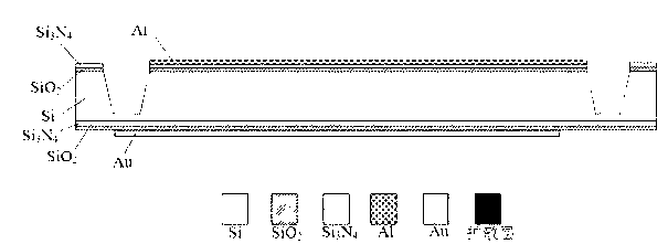
[0032] Such as Figure 1 to Figure 3 Shown, the bipolar electromagnetic scanning micromirror of the present invention comprises microreflection mirror surface 2, bipolar electromagnetic micro-drive coil and support frame 6, and reflection mirror surface 2, bipolar electromagnetic micro-drive coil and support frame 6 are all made in On the same silicon structure layer 5 and using the silicon structure layer 5 as ...


PUM


Abstract

The invention discloses a bipolar electromagnetic scanning micro lens which is processed by taking a silicon base material as a substrate and adopting MEMS (microelectronic mechanical system) process, and is provided with a micro reflecting mirror 2, a bipolar electromagnetic micro driver 4, a torsion beam 1, an angular transducer 3, a bipolar electromagnetic micro driver loop connection pole 5 and a supporting frame 6. According to the invention, a bipolar driving manner is adopted to drive the micro lens, so that attraction force and repulsive force are simultaneously acted on the torsion beam, and wide-angle scanning of the micro lens is realized at lower driving voltage; due to the adoption of the bipolar electromagnetic system driving structure, the response time is greatly shortened and the working frequency of the micro lens is greatly improved; and at the same time, the electromagnetic angular transducer is integrated, so that the accurate measurement of the scanning angle is realized. Therefore, the peripheral signal processing circuit of the scanning micro lens is simple and feasible, and the results of the scanning micro lens can be widely applied to the fields of medical imaging, projector spectrograph, graphic code reader and the like.

Description

technical field [0001] The invention relates to the technical field of micro-opto-electromechanical systems, in particular to a bipolar electromagnetic scanning micromirror. Background technique [0002] As one of the important devices of micro-opto-electromechanical systems (MOEMS), scanning micromirrors have been widely used in medical imaging, projectors, spectrometers and graphic code readers. The basic principle is: by precisely controlling the driving force of the mirror surface rotation, the precise control of the rotation angle of the micromirror surface is realized, so as to precisely control the propagation direction of the light. [0003] At present, most scanning micromirrors are driven by electrostatic, electromagnetic, electrothermal and piezoelectric driving principles. The traditional electromagnetic MOEMS scanning micromirror generally only has a unipolar drive, which causes the device to have disadvantages such as large volume, small rotation angle, poor s...

Claims


Application Information

Patent Timeline
Patent Type & Authority Applications(China)
IPC IPC(8): G02B26/08B81B7/02
Inventor 尚正国李东玲温志渝陈李温中泉
Owner CHONGQING UNIV
Why Eureka
Try Eureka