Zero-voltage delay release

A release and zero-voltage technology, applied in the field of release, can solve the problems of high coil heat generation, small starting torque, and complex circuits, etc., and achieve the effects of short charging time, low heat generation, and reduced power consumption

Active Publication Date: 2012-10-03
JIANGSU GUOXING ELECTRIC EQUIP
View PDF4 Cites 5 Cited by
  • Summary
  • Abstract
  • Description
  • Claims
  • Application Information

AI Technical Summary

Problems solved by technology

[0005] The technical problem to be solved by the present invention is: in order to overcome the prior art, in order to realize the delay tripping after zero voltage (loss of voltage), by increasing the circuit and changing the control mode, the coil of the electromagnetic undervoltage release will be solved when it is working normally. The invention provides a simple circuit, large starting torque, reliable pull-in, small coil heat generation, fast charging speed, and maintenance after zero voltage. Zero-voltage time-delay release with constant coil power (armature holding force), minimum backup charging capacity or longest delay time

Method used


Image

  • Zero-voltage delay release
  • Zero-voltage delay release

Examples


Embodiment Construction

[0032] The present invention is described in further detail now in conjunction with accompanying drawing. These drawings are all simplified schematic diagrams, which only illustrate the basic structure of the present invention in a schematic manner, so they only show the configurations related to the present invention.

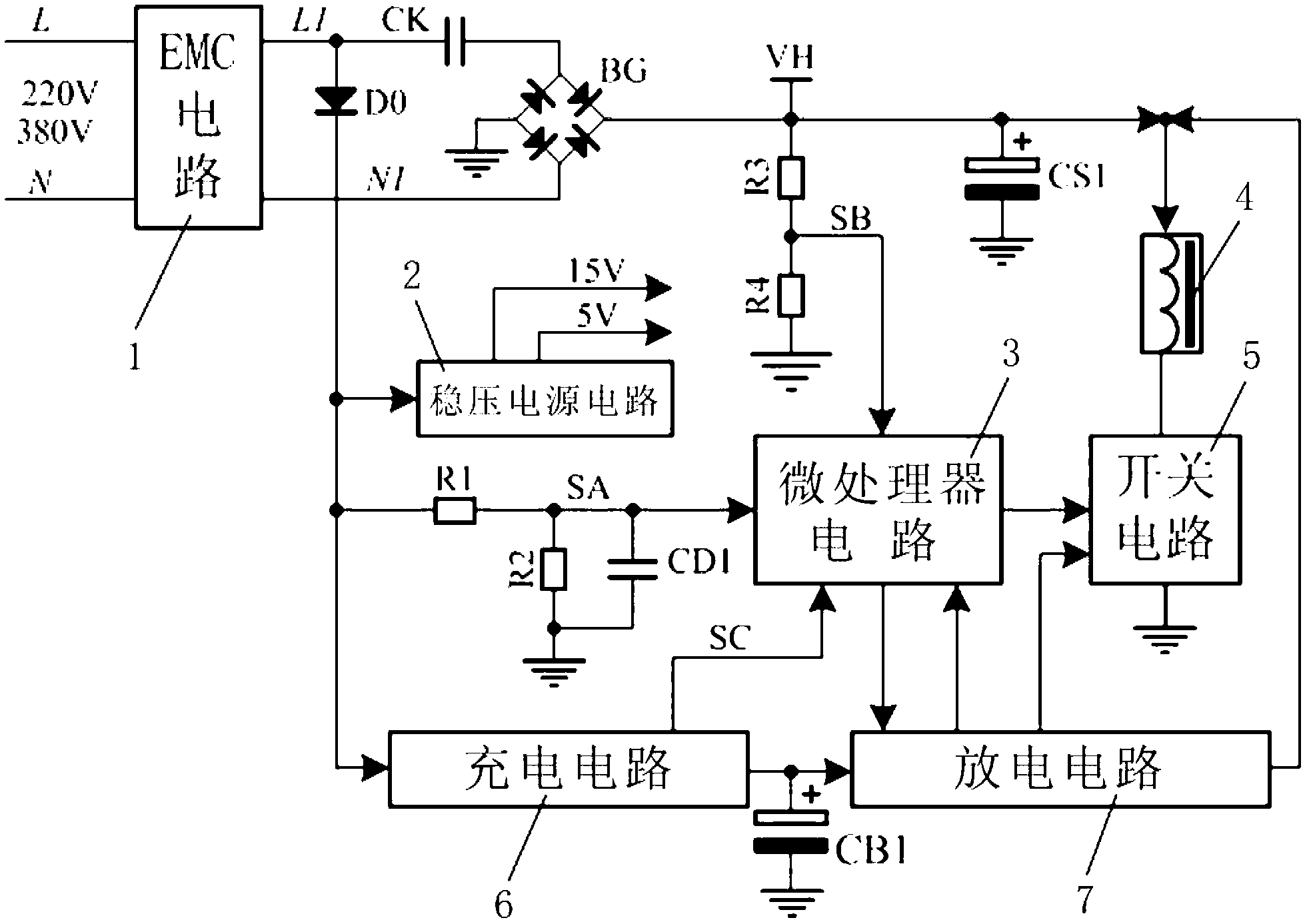
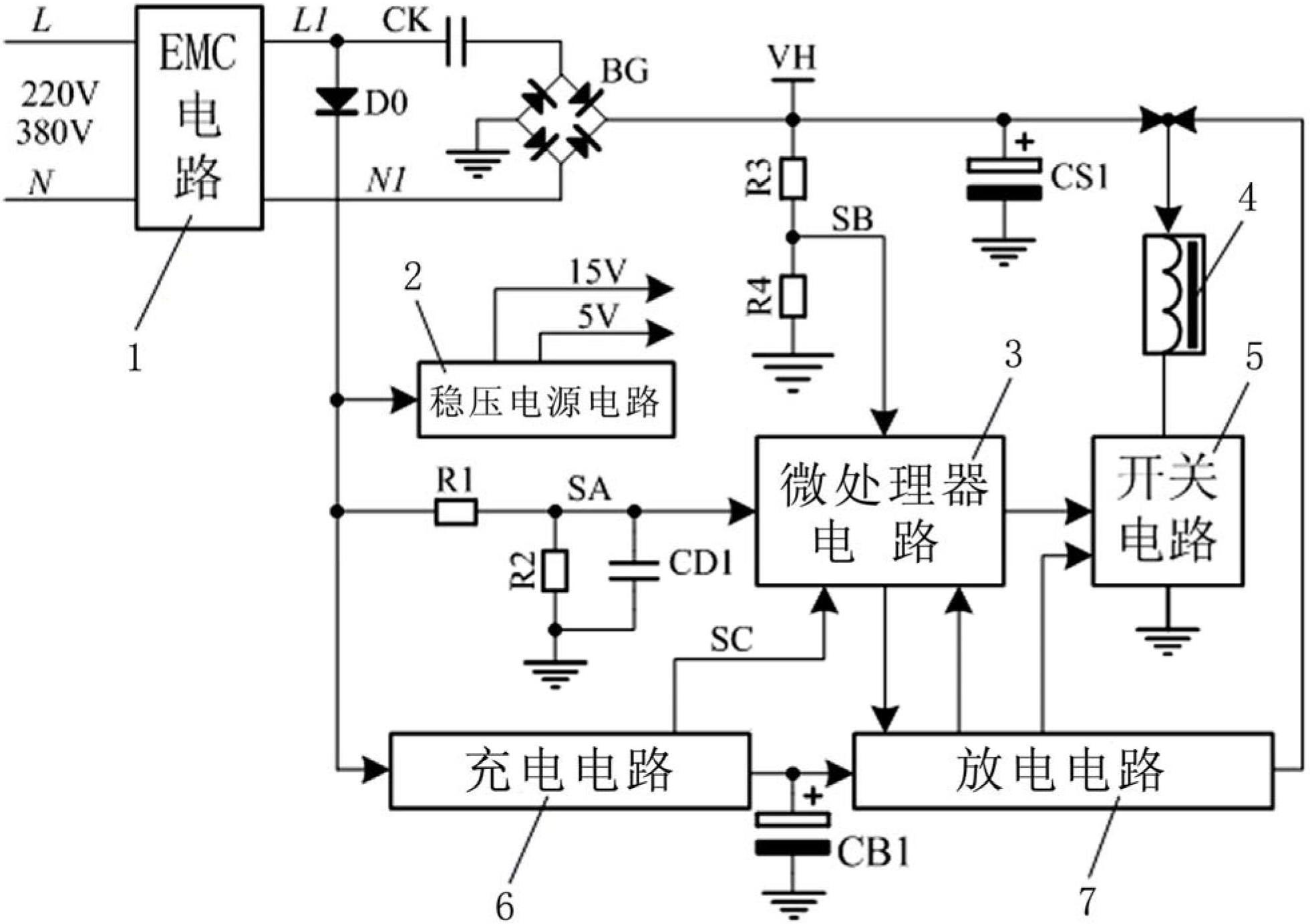
[0033] Such as figure 1 As shown, the circuit principle diagram of the optimal embodiment of a zero-voltage time-delay release of the present invention. EMC circuit 1, step-down capacitor CK, bridge rectifier circuit BG, starting capacitor CS1, SB signal sampling circuit for detecting the voltage of starting capacitor CS1, SA signal sampling circuit for detecting grid voltage, regulated power supply circuit 2, and fast charging circuit 6 , a backup capacitor CB1, a constant current discharge circuit 7, a single-chip circuit 3 and a switch circuit 5 for controlling the on-off of the electromagnet 4. The EMC circuit 1 bidirectionally suppresses the interferenc...


PUM


Abstract

The invention relates to the field of releases, in particular to a zero-voltage delay release, which comprises a filter circuit, a starting power circuit, an electromagnet for releasing control, a switching circuit, a delay circuit for controlling delay releasing, a control circuit for controlling the turn-on / off of the switching circuit, and a regulated power circuit for supplying power to the switching circuit and the control circuit, wherein the power input end of the filter circuit is connected with a power grid, and the power output end of the filter circuit is connected with the power input end of the starting power circuit; and the power output end of the starting power circuit, the switching circuit and a coil of the electromagnet form a series loop. The zero-voltage delay release is simple in circuit, high in starting torque, reliable in closing, low in coil heat and high in charging speed; and after zero voltage, the power of the coil (the retention of an armature) is maintained to be constant, and delay time is long.

Description

technical field [0001] The invention relates to the field of releases, in particular to a zero-voltage time-delay release. Background technique [0002] The undervoltage release is the core component of the low-voltage switch. There are two types of working methods for the undervoltage release to drive the ejector rod: electromagnetic type and permanent magnet type. Compared with the permanent magnet undervoltage release, the electromagnetic undervoltage release has a simple circuit. After the power is cut off, the ejector rod has the ability of "self-resetting" under the action of the spring force. However, existing electromagnetic undervoltage releases generally have problems such as high coil heat generation, low starting torque of the undervoltage release, or too complicated circuits. [0003] According to GB14148.1-2006 "General Rules for Low-Voltage Switchgear and Control Equipment", the action range of the undervoltage release is 35% to 70% of the rated voltage, and ...

Claims


Application Information

Patent Timeline
IPC IPC(8): H02H3/247
Inventor 吴志祥徐磊蒋雷蒋国良
Owner JIANGSU GUOXING ELECTRIC EQUIP
Why Eureka
Try Eureka