PWM (pulse-width modulation) interlocking drive circuit

A technology of drive circuit and interlock circuit, which is applied in the direction of electrical components, output power conversion devices, etc., can solve problems such as MOS module damage, and achieve the effect of ensuring safety and fast operation speed

Inactive Publication Date: 2012-10-03
CHERY AUTOMOBILE CO LTD
View PDF2 Cites 16 Cited by
  • Summary
  • Abstract
  • Description
  • Claims
  • Application Information

AI Technical Summary

Problems solved by technology

The disadvantage of this driving method is that due to the existence of MOSFET parasitic capacitance, the MOSFET cannot be turned off immediately, resulting in the simultaneous conduction of the upper and lower bridge arms, resulting in damage to the MOS module.

Method used


Image

  • PWM (pulse-width modulation) interlocking drive circuit
  • PWM (pulse-width modulation) interlocking drive circuit
  • PWM (pulse-width modulation) interlocking drive circuit

Examples


Embodiment Construction

[0015] Below with reference to the accompanying drawings, through the description of the implementation examples, the specific embodiments of the present invention, such as the shape, structure, mutual position and connection relationship between each part, the role and working principle of each part, etc., will be further described. detailed instructions.

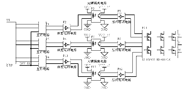
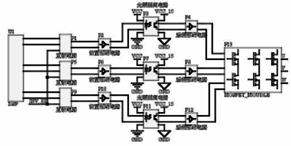
[0016] Such as figure 1 , the PWM interlock circuit of the present invention includes a digital signal processor DSP that generates PWM signals, and the digital signal processor DSP has three pairs of PWM signal outputs, and each pair of PWM signals is connected to each pair of up and down of the MOSFET module P13 through an interlock circuit bridge arm. By adopting the digital signal processor DSP with fast operation speed and built-in PWM signal generator as the drive core, the duty cycle and output frequency of the PWM output can be programmed by software; the output of the digital signal processor DSP controls the PWM...


PUM


Abstract

The invention provides a PWM (pulse-width modulation) interlocking drive circuit which is stable and reliable, lower in drive power, long in service life and fast in switching speed and comprises a digital signal processor which can be used for generating a PWM signal, wherein the digital signal processor has N pairs of PWM signal outputs and each PWM signal is connected with each pair of upper and lower bridge arms of a MOSFET (metal-oxide-semiconductor field effect transistor) module. The digital signal processor which is fast in operational speed and has a PWM signal generator is adopted as a drive core, the duty cycle and the output frequency of the PWM can be programmed by software; and PWM pulses of the upper and lower bridge arms of the MOSFET module are controlled to adjust appropriate dead time, so that the condition that the upper and lower bridge arms of the MOSFET module are not conducted is ensured; and meanwhile, the PWM can be connected to the upper and lower bridge arms of the MOSFET module through an interlocking circuit, namely that the PWM signals are not simultaneously input to the upper and lower bridge arms of the MOSFET module from the aspect of circuit, and safety of the MOSFET module is ensured.

Description

technical field [0001] The invention relates to the technical field of motor drive, and specifically designs a PWM interlock drive circuit. Background technique [0002] As one of the power semiconductor devices with the most application prospects in the motor drive system, the performance of the MOSFET module determines whether the motor drive system can work safely and stably. In the electric vehicle motor drive system, the most frequently encountered problem is the damage of the MOSFET power module (hereinafter referred to as the MOS module). In order to solve this problem, technicians have done a lot of research work on MOS module drive protection. The research found that the main reason for module damage is that the module is burned due to direct short circuit caused by simultaneous conduction of the upper and lower bridge arms of the same phase. [0003] At present, the driving method of the module has been used in many mature applications. The most common one is that...

Claims


Application Information

Patent Timeline
Patent Type & Authority Applications(China)
IPC IPC(8): H02M1/38
Inventor 凌欢吴瑞邵平袁文爽
Owner CHERY AUTOMOBILE CO LTD
Why Eureka
Try Eureka