Sea-island composite fiber, ultrafine fiber, and composite die
A composite fiber and composite spinning technology, which is applied in spinneret assemblies, conjugated synthetic polymer rayon, fiber processing, etc. Head or fall off, stress distribution suppression, high productivity effect
- Summary
- Abstract
- Description
- Claims
- Application Information
AI Technical Summary
Problems solved by technology
Method used
Image
Examples
Embodiment 1
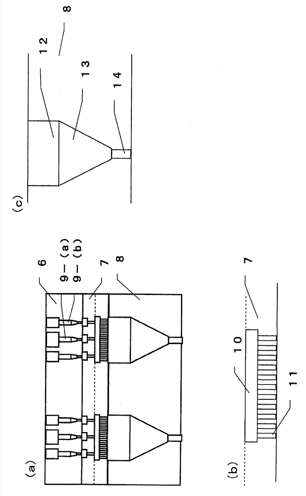
[0178] Polyethylene terephthalate (PET1 Melt viscosity: 120 Pa?s, Toray Co., Ltd. T301T) as the island component, and 5.0 mol% of sodium isophthalate 5-sulfonate as the sea component were copolymerized The PET (copolymerized PET1 melt viscosity: 140Pa?s A260 manufactured by Toray Co., Ltd.) was melted at 290°C, measured, and poured into the assembly figure 2 The spin pack of the composite spinneret shown discharges the composite polymer stream from the discharge orifice. It should be noted that four measuring plates are stacked, and the flow path is set in such a way as to expand downstream, and the sea component and the island component are measured step by step through the orifice (φ0.4 L / D=1.5) in each measuring plate. polymer. In addition, 10 distribution plates are stacked, and a flow channel for distributing a fine polymer flow in the fiber cross-sectional direction is provided. 1000 distribution holes for the island components are perforated on the distribution plate...
Embodiment 2~4
[0183] From the method described in Example 1, except that the composite ratio of the sea / island component is changed stepwise to 20 / 80 (Example 2), 50 / 50 (Example 3), and 70 / 30 (Example 4) , implement according to embodiment 1. The evaluation results of these island-in-the-sea composite fibers are shown in Table 1. Similar to Example 1, the circumscribed circle diameter and shape homogeneity of the island components were excellent, and there was no change (◯) even after 72 hours. The results are shown in Table 1.
[0184] [Table 1]
[0185]
Embodiment 5
[0197] In addition to using polyethylene terephthalate (PET2 Melt viscosity: 110Pa?s, Toray Co., Ltd. T900F) as the island component, 8.0 mol% of 5-sodium sulfoisophthalate is copolymerized as the sea component. PET (copolymerized PET2 melt viscosity: 110 Pa?s), except that the draw ratio was 4.0 times, all were implemented as in Example 1. The sea-island composite fiber can be stretched at a high ratio, so that the strength can be relatively increased. Other evaluation results are shown in Table 3. As in Example 1, the circumscribed circle diameter and shape homogeneity of the island components were excellent.
[0198] In addition, the manufacturing method of the copolymerized PET2 used as a sea component in Example 5 is as follows.
[0199] Add 8.7 kg of dimethyl terephthalate, 1.2 kg of dimethyl isophthalate-5-sodium sulfonate (equivalent to 8 mol% relative to the total acid content of the obtained polymer), 5.9 kg of ethylene glycol, 50 g of lithium acetate was heated to...
PUM
| Property | Measurement | Unit |
|---|---|---|
| Circle diameter | aaaaa | aaaaa |
| Fiber diameter | aaaaa | aaaaa |
| Breaking strength | aaaaa | aaaaa |
Abstract
Description
Claims
Application Information
 - R&D
- Intellectual Property
- Life Sciences
- Materials
- Tech Scout
- Unparalleled Data Quality
- Higher Quality Content
- 60% Fewer Hallucinations
Browse by: Latest US Patents, China's latest patents, Technical Efficacy Thesaurus, Application Domain, Technology Topic, Popular Technical Reports.
© 2025 PatSnap. All rights reserved.Legal|Privacy policy|Modern Slavery Act Transparency Statement|Sitemap|About US| Contact US: help@patsnap.com


