Hydraulic winch

A technology of hydraulic winches and hydraulic brakes, applied in the field of hydraulic winches, can solve problems affecting clutch performance, complex connection structure, and difficult processing, etc., achieve stable and reliable clutch performance, simplify the axial limit structure, and improve processing technology.

Active Publication Date: 2012-10-10
INI HYDRAULIC
View PDF6 Cites 21 Cited by
  • Summary
  • Abstract
  • Description
  • Claims
  • Application Information

AI Technical Summary

Problems solved by technology

[0003] In order to solve the problems of the complex and difficult processing of the hydraulic winch with clutch, the unbalanced force of the power shaft in the hydraulic winch, the axial thrust on the frame and the inability to realize the modularization of the clutch components, the inventor proposed a method called " The technology of "Hydraulic Winch with Clutch at the Final Stage of Transmission" (Authorized Notification No. CN 101190770 B) shows a hydraulic winch with clutch at the final stage of transmission with balanced force on the power shaft, simple structure, and convenient processing and disassembly. It is composed of hydraulic motor, hydraulic brake, planetary gear reducer, hydraulic clutch, reel and hydraulic control circuit to control its work. The hydraulic clutch set in the reel is at the end of the system transmission chain, and the planetary gear reducer is set in the reel. Inside the barrel, the right output end of the last stage planet carrier is the spline shaft connected to the multi-plate friction clutch, the right end of the spline shaft is the piston of the clutch control cylinder, the planet carrier of the planetary gear reducer and the spline of the clutch Shaft and piston are integrated structure
This authorized patent effectively solves the problems of complex connection structure, difficult processing and assembly, unbalanced force on the power shaft, easy wear of the connection due to axial force on the frame, low mechanical efficiency and short service life of the existing hydraulic winch. ; In the long-term production practice and use process, it is found that there are still some deficiencies: first, the outer cylinder is fixedly installed on the reel, and the spline shaft is fixedly installed in the reducer, making it difficult to obtain a higher quality of the outer cylinder and the spline shaft The coaxiality of the fixed friction plate and the moving friction plate on the two are difficult to obtain a high parallelism, which affects the performance of the clutch, makes the clutch friction plate more prone to heat and wear, and seriously affects the service life of the winch; followed by The spline shaft of the clutch and the final planetary carrier are of an integral structure, and the other end is sleeved on the oil delivery shaft. This integral structure makes the spline shaft protrude longer in the axial direction and is in a suspended state. The suspension end has no Radial positioning, due to the accumulation of processing errors of each transmission chain, there is a large coaxiality deviation between the axis of the clutch spline shaft and the axis of the reel, so it is easy to produce a large jump during operation, which further reduces the cost. The parallelism between the fixed friction plate and the dynamic friction plate on the key shaft; again, due to the large radial runout of the clutch spline shaft during operation, the seal between the oil transmission sleeve and the oil transmission shaft that controls the opening and closing of the clutch is very tight. It is easy to be damaged, resulting in the problem of oil leakage; in addition, due to the limitation of the structure, there are problems of poor processing and assembly process

Method used


Image

  • Hydraulic winch
  • Hydraulic winch

Examples


Embodiment

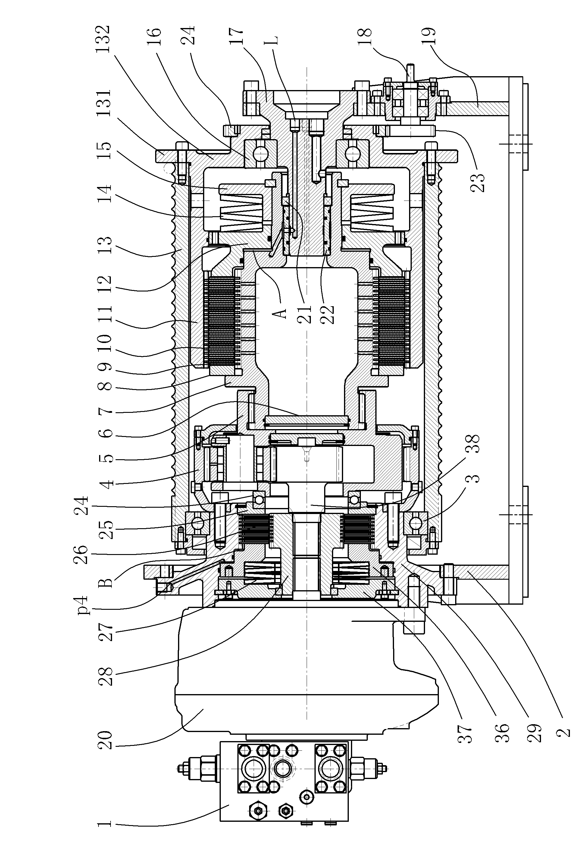
[0031] Embodiment: a kind of hydraulic winch of the present invention, as attached figure 1 As shown, it includes a frame, a reel 13 for winding a wire rope, a hydraulic motor 20, a hydraulic control block 1, a hydraulic brake, a planetary gear reducer 4 and a hydraulic clutch located in the reel 13.

[0032] The hydraulic clutch includes an outer cylinder 11 , a fixed friction plate 10 , a moving friction plate 9 and a clutch oil cylinder that drives the two friction plates to clutch. The clutch oil cylinder includes a cylinder body 12 , a piston 7 and a disc spring 14 . The middle part of the cylinder body 12 is provided with a side wall, and a clutch oil chamber A is provided between the side wall and the piston 7 . The disc spring 14 is fixed on the piston 7 by a stopper 15 .

[0033] The support shaft 17 is fixed on the frame, and the support shaft 17 is coaxially arranged with the outer cylinder 11 and the piston 7. The outer cylinder 11 is fixed on the middle part of t...


PUM


Abstract

The invention relates to a hydraulic winch, comprising a machine frame, a winding barrel, a hydraulic motor, and a hydraulic brake, a planet gear speed reducer and a hydraulic clutch which are arranged in the winding barrel. The hydraulic clutch comprises an outer barrel, a clutch friction plate and a clutch oil cylinder. A bearing shaft is fixed on the machine frame. The outer barrel and a piston of the clutch oil cylinder are fixed on the bearing shaft through bearings respectively. The piston is in transmission connection with an output end of a planet carrier of the planet gear speed reducer. The outer barrel and the piston are fixed on the bearing shaft, so that the outer barrel, the piston and the bearing shaft have a relatively high coaxiality, and a dynamical friction plate and a static friction plate which are arranged on the outer barrel and the piston respectively have relatively high parallelism. The dynamical friction plate and the static friction plate can be well contacted with each other and completely separated from each other as well so that the hydraulic winch has more stable and reliable clutch performance, and the abrasion and the heat generation of the clutch friction plate are reduced. In the hydraulic winch, transmission efficiency and operational reliability can be improved, and service life can be prolonged. The hydraulic winch has a simplified integral structure and higher machining and assembling manufacturability.

Description

technical field [0001] The invention relates to a winch for winding a wire rope, in particular to a hydraulic winch. [0002] Background technique [0003] In order to solve the problems of the complex and difficult processing of the hydraulic winch with clutch, the unbalanced force of the power shaft in the hydraulic winch, the axial thrust on the frame and the inability to realize the modularization of the clutch components, the inventor proposed a method called " The technology of "Hydraulic Winch with Clutch at the Final Stage of Transmission" (Authorized Notification No. CN 101190770 B) shows a hydraulic winch with clutch at the final stage of transmission with balanced force on the power shaft, simple structure, and convenient processing and disassembly. It is composed of hydraulic motor, hydraulic brake, planetary gear reducer, hydraulic clutch, reel and hydraulic control circuit to control its work. The hydraulic clutch set in the reel is at the end of the system tr...

Claims


Application Information

Patent Timeline
Patent Type & Authority Applications(China)
IPC IPC(8): B66D1/00B66D1/08B66D1/22B66D1/30B66D5/28
Inventor 胡世璇
Owner INI HYDRAULIC
Why Eureka
Try Eureka