
Special integrated circuit for vehicle flasher

An integrated circuit and flasher technology, which is applied to optical signals, vehicle components, signal devices, etc., can solve the problem of the long-term stability of the flash frequency and the difficulty in ensuring temperature changes, the inability to guarantee the temperature characteristics of the flasher flash frequency, and the temperature of the electrolytic capacitor. Poor characteristics and other problems, to achieve the effect of good temperature characteristics, convenient application, and small electromagnetic interference

Active Publication Date: 2012-10-17
CHONGQING SANXIN ELECTRONICS
View PDF13 Cites 1 Cited by
  • Summary
  • Abstract
  • Description
  • Claims
  • Application Information

AI Technical Summary

Problems solved by technology

[0002] Cars are an important means of transportation in modern times. The existing flashers include contact flashers and electronic flashers. Among them, the contact flasher controls the flasher frequency by adjusting the contact gap and the spring plate, but the long-term It is difficult to guarantee the stability and temperature change; the existing electronic flasher is composed of discrete circuits. In the MOSFET flasher of the separated circuit, because the flash frequency is very low, uF-level electrolytic capacitors must be used as oscillation timing capacitors; uF-level The temperature characteristics of electrolytic capacitors are very poor, so that the temperature characteristics of the flash frequency cannot be guaranteed

Method used


Image

  • Special integrated circuit for vehicle flasher
  • Special integrated circuit for vehicle flasher
  • Special integrated circuit for vehicle flasher

Examples


Embodiment Construction

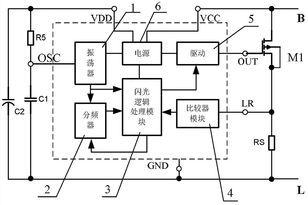
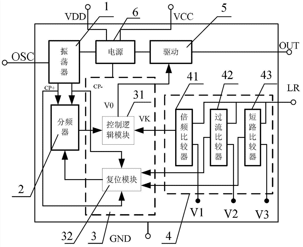
[0033] see figure 1 and figure 2 , a special integrated circuit for a flasher for a vehicle, including a power input terminal VCC for supplying power, a power output terminal VDD for supplying power to peripheral circuits, a ground terminal GND, a peripheral RC oscillator circuit interface OSC, a detection terminal LR, an output terminal OUT and a pair of The following circuits are integrated circuits, these circuits include: oscillator 1, frequency divider 2, flash logic processing module 3, comparator module 4, drive circuit 5 and power supply 6; wherein:

[0034] The oscillator 1 receives the oscillating signal output by the peripheral RC oscillating circuit through the peripheral RC oscillating circuit interface OSC, generates a clock signal, and outputs it to the frequency divider 2 and the flash logic processing module 3;

[0035] The frequency divider 2 receives the clock signal output by the oscillator 1, and simultaneously receives the reset signal output by the fla...


PUM


Abstract

The invention discloses a special integrated circuit for a vehicle flasher. The integrated circuit comprises a power input terminal for supplying power, a power output terminal for supplying power to a peripheral circuit, a ground terminal, a peripheral RC (resistor-capacitor) oscillation circuit interface, a detection terminal, an output terminal and a circuit for integrating the following circuits: an oscillator, a frequency divider, a flash logic processing module, a comparator module, a drive circuit and a power. The integrated circuit is characterized in that the oscillator receives oscillation signals output by a peripheral RC oscillation circuit via the peripheral RC oscillation circuit interface to generate clock signals and outputs the clock signals to the frequency divider and the flash logic processing module; and the frequency divider receives the clock signals output by the oscillator, simultaneously receives reset signals output by the flash logic processing module, processes the clock signals and the reset signals to generate pulse signals and outputs the pulse signals to a flash logic processing circuit. The integrated circuit has the characteristics of good temperature property and high reliability, and can be widely applied to the flashers of vehicles, motorcycles and electric bicycles.

Description

technical field [0001] The invention relates to an integrated circuit, in particular to an integrated circuit for a vehicle flasher. Background technique [0002] Cars are an important means of transportation in modern times. The existing flashers include contact flashers and electronic flashers. Among them, the contact flasher controls the flasher frequency by adjusting the contact gap and the spring plate, but the long-term It is difficult to guarantee the stability and temperature change; the existing electronic flasher is composed of discrete circuits. In the MOSFET flasher of the separated circuit, because the flash frequency is very low, uF-level electrolytic capacitors must be used as oscillation timing capacitors; uF-level The temperature characteristic of the electrolytic capacitor is very poor, so that the temperature characteristic of the flash frequency of the flasher cannot be guaranteed. Contents of the invention [0003] The technical problem to be solved b...

Claims


Application Information

Patent Timeline
Patent Type & Authority Applications(China)
IPC IPC(8): B60Q1/00
Inventor 郑雷
Owner CHONGQING SANXIN ELECTRONICS
Learn More