Device and method for carrying out granulation treatment and residual heat utilization on liquid-state furnace slag

A slag and granulation technology is applied in the field of liquid slag granulation treatment and waste heat utilization devices, and achieves the effects of easy recycling, uniform slag particle size and low energy consumption

Inactive Publication Date: 2012-10-17
江苏东能环保能源科技有限公司
View PDF5 Cites 19 Cited by
  • Summary
  • Abstract
  • Description
  • Claims
  • Application Information

AI Technical Summary

Problems solved by technology

At present, there is no high-temperature steel slag granulation and waste heat recovery technolo

Method used


Image

  • Device and method for carrying out granulation treatment and residual heat utilization on liquid-state furnace slag
  • Device and method for carrying out granulation treatment and residual heat utilization on liquid-state furnace slag
  • Device and method for carrying out granulation treatment and residual heat utilization on liquid-state furnace slag

Examples


Embodiment 1

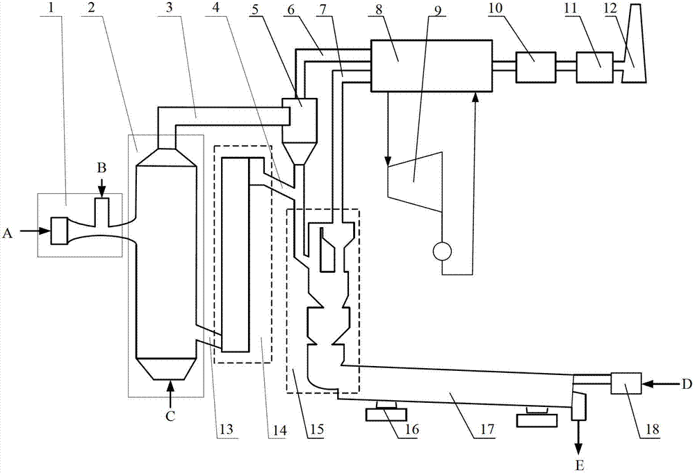
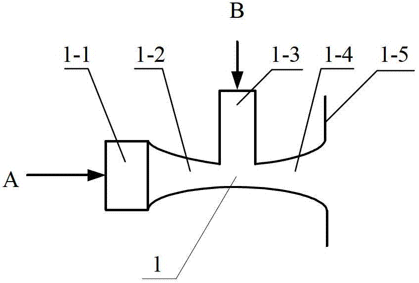
[0039] This embodiment provides a liquid slag granulation treatment and waste heat utilization device, connected as figure 1 As shown, it includes a granulation assembly 1, a slag storage tank 2, an exhaust gas separator 5, a waste heat boiler 8, a steam turbine 9, a dust collector 10, an induced draft fan 11, a chimney 12, a bucket elevator 14, and a gas-solid separation cooling chamber 15 , a converter 17, a blower 18; the granulation assembly 1 is provided with a high-pressure air or high-pressure water inlet A, a liquid slag inlet B and a granulated slag outlet, the granulated slag outlet is connected to the slag storage tank 2, and the bottom of the slag storage tank 2 is provided with Air inlet C, the lower part of the slag storage tank 2 is connected to the bucket elevator 14 through the high-temperature solid slag discharge pipe 13, the top of the slag storage tank 2 is connected to the tail gas separator 5 through the connecting pipe 3 of the granulated crude tail gas,...

Embodiment 2

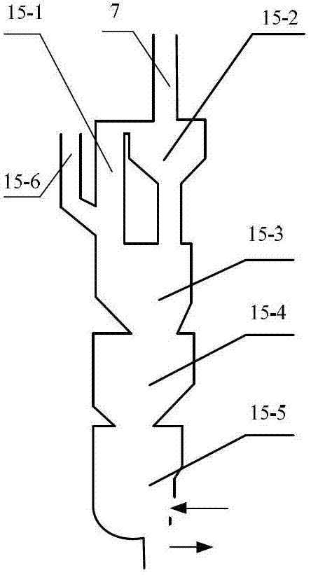
[0050] The difference between this embodiment and Embodiment 1 is that the structure of the gas-solid separation cooling chamber 15 is different. The gas-solid separation cooling chamber 15 of the present embodiment is composed of a riser 15-8, a three-stage gas-solid separation cooler 15- 7. The secondary gas-solid separation cooler 15-10, the primary gas-solid separation cooler 15-11 and the standpipe 15-9; the inlet of the standpipe 15-9 is connected to the lower part of the tail gas separator 5 and the top of the bucket elevator 14 , the outlet of the riser 15-6 is connected to the riser 15-8, the upper part of the riser 15-8 is connected to the third-stage gas-solid separation cooler 15-7, the lower part is connected to the second-stage gas-solid separation cooler 15-10, and the third-stage gas-solid separation cooler 15-10 is connected to the lower part of the riser 15-8 The upper part of the separation cooler 15-7 is connected to the high-temperature air connecting pipe ...

Embodiment 3

[0052] The difference between this embodiment and Embodiment 1 is that the structure of the gas-solid separation cooling chamber 15 is different. Bed 15-14, gas-solid separation cooler 15-15, air distribution plate 15-16 and blanking connecting pipe 15-17; the inlet of feeding riser 15-12 is connected to the lower part of tail gas separator 5 and bucket elevator 14 At the top, the baffle bed 15-14 is provided with multi-layer air distribution plates 15-16 from top to bottom, the outlet of the feed riser 15-12 is connected to the top air distribution plate 15-16, and the connection is provided with a baffle The plate 15-13, the upper part of the baffle bed 15-14 is connected to the gas-solid separation cooler 15-15, the upper part of the gas-solid separation cooler 15-15 is connected to the high-temperature air connecting pipe 7, and the lower part is connected to the air distribution plate 15-16, and the baffle The lower part of the beds 15-14 is connected to the converter 17....


PUM


Abstract

The invention discloses a device and a method for carrying out granulation treatment and residual heat utilization on liquid-state furnace slag. The liquid-state furnace slag is chilled and granulated in a granulation assembly through introduced high-pressure air or high-pressure water; granulated grains enter a slag storing pot; slag grains are lifted into a gas-solid separation cooling chamber through a bucket elevator; granulating rough tail gas at an outlet of the upper end of the slag storing pot passes through a tail gas cyclone separator and the separated solid grains are conveyed into the gas-solid separation cooling chamber; the granulating tail gas is conveyed into a residual heat boiler; the gas-solid separation cooling chamber is connected with a converter and the air enters from an air inlet of the converter and sequentially passes through the converter and the gas-solid separation cooling chamber, so that the solid slag grains are further cooled; the gas absorbing the residual heat of the furnace slag is discharged from the upper end of the gas-solid separation cooling chamber and enters the residual heat boiler; finally, the cooled furnace slag is discharged from a grain outlet of the converter; and steam generated by the residual heat boiler enters a steam turbine to generate power.

Description

Technical field [0001] The invention involves a dregs treatment method, especially for a liquid furnace slag granification treatment and the use of residual heat use devices and methods. Background technique [0002] The slag is an inevitable by-byte in the process of steelmaking, and its discharge volume is about 15%-20%of the output of crude steel.The formation temperature of the furnace slag is 1500 ° C-1700 ° C, which has high heat explicit heat. Therefore, the steel residue is one of the main products in the process of steel production. It belongs to the high-quality resource resource and has high recovery and utilization value.Reasonable use and effective recycling of furnaces can achieve sustainable development of the steel industry, reduce production costs, and improve corporate economic benefits. At the same time, it can also reduce pollution and turn waste into treasure. [0003] The liquid stab needs to cool through the cooling treatment to form a block with a particle...

Claims


Application Information

Patent Timeline
IPC IPC(8): C21B3/08
CPCC21B2400/024C21B2400/026C21B2400/062C21B2400/074C21B2400/08
Inventor 向文国肖军顾昊
Owner 江苏东能环保能源科技有限公司
Why Eureka
Try Eureka