
GIS (Geographic Information System) fault diagnosis system and method based on vibration signal spectrum analysis

A fault diagnosis system and vibration signal technology, applied in the field of GIS fault monitoring, can solve problems such as the inability of ultra-high frequency sensors to suppress interference, the impact on the accuracy of detection results, and inconvenient installation on site, and achieve simple composition and structure, obvious features, and easy The effect of engineering realization

Active Publication Date: 2012-10-17
JIANGSU ELECTRIC POWER CO +2
View PDF4 Cites 35 Cited by
  • Summary
  • Abstract
  • Description
  • Claims
  • Application Information

AI Technical Summary

Problems solved by technology

[0007] 1. The UHF detection method can perform fault diagnosis according to the waveform characteristics of the discharge pulse and the spectrum characteristics of the UHF signal. It has good detection sensitivity, but the structural design of the UHF sensor itself cannot suppress the interference from the high frequency band in the substation. This seriously affects the accuracy of the test results.
[0008] 2. High-frequency grounding current method, using well-made sensors can maintain good transmission characteristics in a wide frequency range, but the ground wire needs to pass through the coil, which makes on-site installation extremely inconvenient
[0009] 3. The optical measurement method does not have the problem of anti-interference, but the sensitivity is very low and a large number of sensors are required, so this method is not practical

Method used


Image

  • GIS (Geographic Information System) fault diagnosis system and method based on vibration signal spectrum analysis
  • GIS (Geographic Information System) fault diagnosis system and method based on vibration signal spectrum analysis
  • GIS (Geographic Information System) fault diagnosis system and method based on vibration signal spectrum analysis

Examples


Embodiment Construction

[0033] The present invention will be further described below.

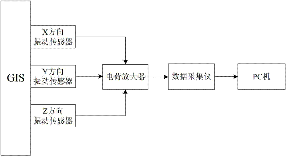
[0034] The structure of the GIS fault diagnosis system of the present invention is as figure 1 As shown, it includes a vibration acceleration sensor, a charge amplifier, a data acquisition instrument and a PC, wherein: the vibration acceleration sensor is firmly adsorbed (fixed) on the outer surface of the GIS box through a magnet, and the output end of the vibration acceleration sensor is connected to the charge amplifier. The amplifier is connected to the data acquisition instrument through the BNC electrical conversion interface, and the data acquisition instrument is connected to the PC through the network cable interface. The vibration acceleration sensor cooperates with the charge amplifier to measure vibration signals. The data acquisition instrument is used to collect and record the detected vibration signals. The PC is used to store, process and diagnose the signal data output by the data acquisition inst...


PUM


Abstract

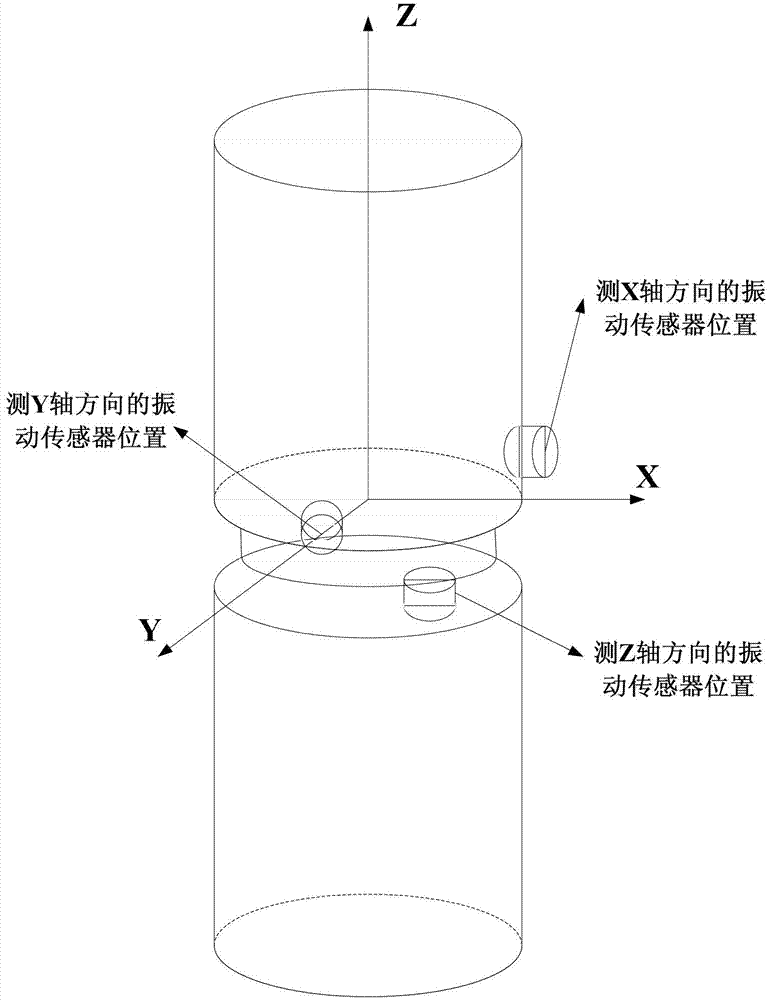
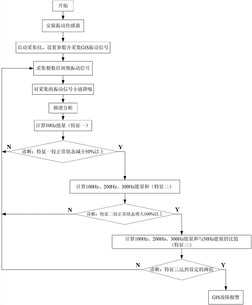
The invention discloses a GIS (Geographic Information System) fault diagnosis system and method based on vibration signal spectrum analysis, belonging to the field of GIS fault monitoring. The system comprises a vibration acceleration sensor, a charge amplifier, a data acquisition instrument and a PC (Personal Computer) all of which are successively connected together in series, wherein the vibration acceleration sensor comprises three vibration sensors which are fixed on the outer surface of a GIS box in the X-axis, Y-axis and Z-axis directions, respectively. The diagnosis method of the system comprises the following steps of: acquiring GIS vibration signals in the X-axis, Y-axis and Z-axis directions by means of the three vibration sensors; performing wavelet de-noising on the vibration signals intercepted by a full period and then performing spectrum analysis; calculating energy at 50 Hz and the sum of energy at 100 Hz, energy at 200 Hz and energy at 300 Hz respectively; comparing the calculated values with the normal state; and determining the GIS fault according to the result of comparison in combination with a threshold. The method is easy in engineering realization, obvious in feature and capable of effectively diagnosing the GIS fault.

Description

technical field [0001] The invention relates to an on-line monitoring technology for the state of power transmission and transformation equipment, in particular to a fault diagnosis system and method for a gas-insulated metal-enclosed switchgear (GIS), which belongs to the field of GIS fault monitoring. Background technique [0002] Gas-insulated metal-enclosed switchgear (GIS) was born in the early 1970s. It is a combination of electrical components such as circuit breakers, disconnectors, fast earthing switches, current transformers, lightning arresters, busbars, bushings, and cable terminals. In the metal shell, the interior is filled with 0.3~0.4MPa SF6 gas as the insulating medium. [0003] The role of GIS is equivalent to a switch station, which has the advantages of small size, small footprint, high operational reliability, no influence from external environment, flexible configuration, small maintenance workload, long maintenance cycle, and no electromagnetic interfe...

Claims


Application Information

Patent Timeline
IPC IPC(8): G01R31/00G01H1/00
Inventor 陈楷李凯王春宁马宏忠徐天乐陈静民李勇王春亮张赢
Owner JIANGSU ELECTRIC POWER CO
Learn More