

Light collecting device
A technology of light collection and light reflection, applied in the field of solar cells, to achieve the effects of reducing costs, improving conversion efficiency, and avoiding stability decline
- Summary
- Abstract
- Description
- Claims
- Application Information
AI Technical Summary
Problems solved by technology
Method used
Image

Examples
Embodiment 1
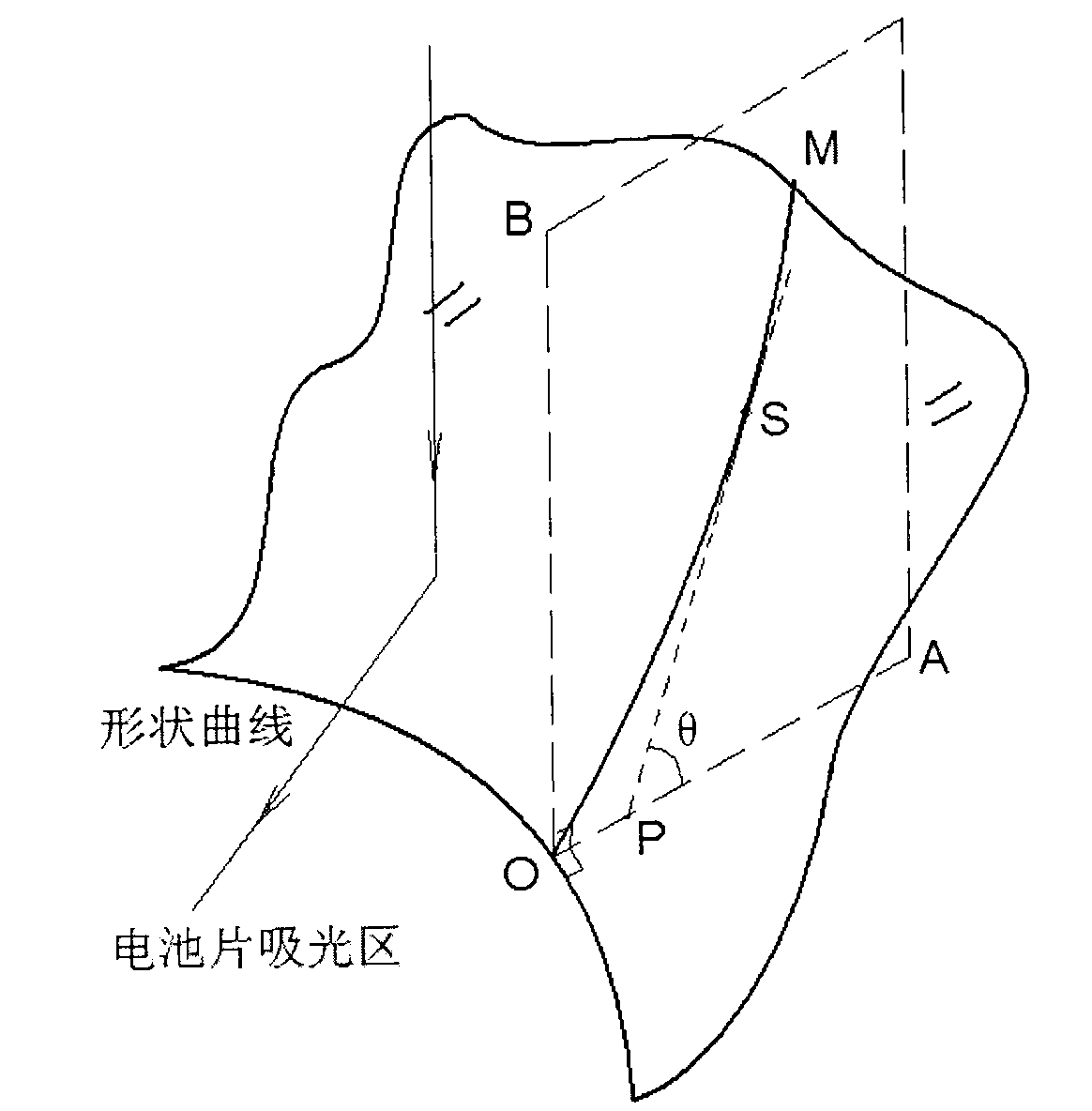
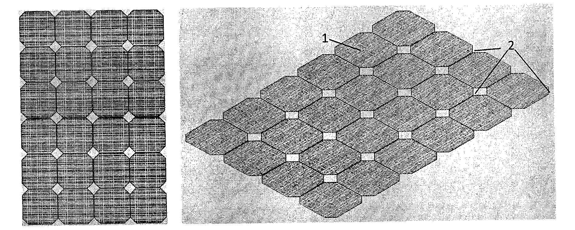
[0032] As mentioned in the background art, for the four-sided cut monocrystalline silicon cells, there will be a small quadrangle-like blank area in the middle of every four monocrystalline silicon cells due to its approximate octagonal shape. Such as Figure 2aAs shown, for this situation, the above-mentioned light collection device can adopt a device with a light reflection function. According to the characteristics of the reflection surface of the light reflection device in the summary of the invention, the light reflection device can be a series of pyramid-like structures, and the shape formed by the bottom edge of each pyramid structure intersecting with the plane of the battery panel is just in line with the blank The small quadrilaterals of the area coincide. The four sides of the pyramid structure except the bottom are reflective surfaces, which reflect the light irradiated on it to the monocrystalline silicon cell. The reflection device of the pyramid structure is m...
Embodiment 2
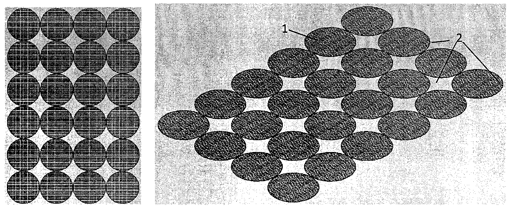
[0035] As mentioned in the background art, for components composed of circular monocrystalline silicon cells, there will be some blank areas between the circular single crystal silicon cells. This part of the blank area can be described as a concave arc quadrilateral according to the arrangement of the circular cells (such as Figure 2b shown), concave arc triangle (such as Figure 2c shown) or some other shape. In this embodiment, the light collection device is designed by taking the blank area as an example of a concave arc triangle. The blank area is a concave arc quadrilateral or some other shapes, which can be similarly designed in the same way. The appearance of the concave arc triangular blank area is formed by the arrangement of circular cells in a hexagonal close-packed manner (honeycomb). In view of this situation, the light collection device can adopt a device with a light reflection function. According to the characteristics of the reflection surface of the lig...
Embodiment 3
[0039] As described in the background technology, the situation between the situation described in Embodiment 1 and Embodiment 2 is not to cut off the four sides of the circular silicon wafer, nor is it not cut at all, but to cut off one or several sides. Edges, for example forming the shape of a crown or semicircle. When the monocrystalline silicon cells of these shapes are combined into battery components, there will also be some irregular blank areas between the monocrystalline silicon cells. In this embodiment, the semicircular cells are arranged side by side in the same direction as an example. There will be a blank area between every four semicircular battery pieces, and the shape of this area is composed of two 90-degree arcs and a straight line, which is called an isosceles concave arc triangle (such as Figure 2d shown). In view of this situation, the light collection device can adopt a device with a light reflection function. According to the characteristics of th...
PUM
 Abstract
Description
Claims
Application Information