Airborne navigation antenna

An antenna and antenna radiator technology, which is applied in directions such as antennas and radiating element structures suitable for movable objects, can solve problems such as affecting the overall layout of the aircraft, increasing the number of antennas, reducing reliability, etc. High reliability and beautiful appearance

Active Publication Date: 2012-10-17
SHAANXI LINGYUN ELECTRONICS GROUP
View PDF4 Cites 3 Cited by
  • Summary
  • Abstract
  • Description
  • Claims
  • Application Information

AI Technical Summary

Problems solved by technology

[0004] At present, the airborne antenna of the instrument landing system at home and abroad is mainly installed on the vertical tail of the aircraft, and the left and right antennas are installed symmetrically. They are protruding installations, which have a certain impact on the aerodynamic performance

Method used


Image

  • Airborne navigation antenna
  • Airborne navigation antenna
  • Airborne navigation antenna

Examples


Embodiment Construction

[0010] Embodiments of the present invention will be further described below in conjunction with the accompanying drawings.

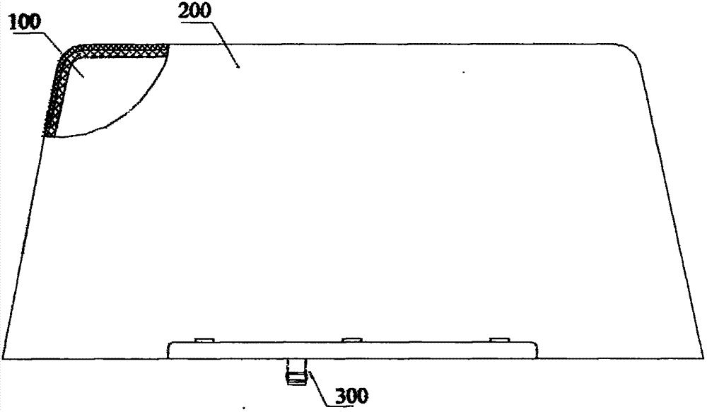
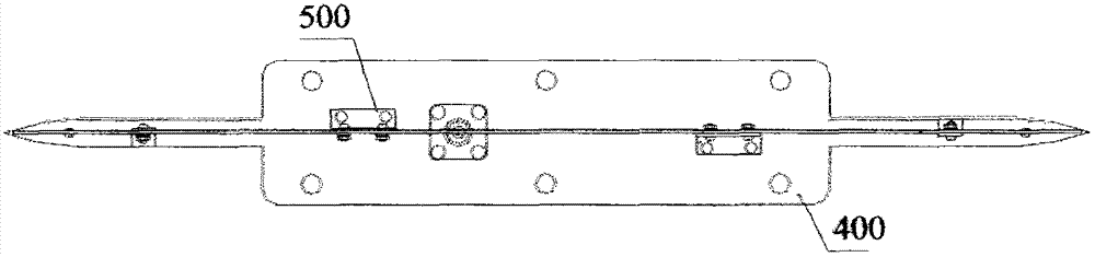
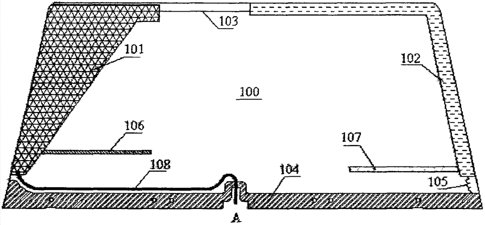
[0011] Such as figure 1 and figure 2 As shown, the airborne navigation antenna of the present invention is an antenna with a planar structure, and the antenna is mainly composed of an antenna radiator 100 , an antenna cover 200 , a high-frequency socket 300 , a bottom plate 400 , and a corner piece 500 . Among them, the antenna cover 200 is a stepped shell, and the material is made of glass fiber reinforced plastics. The bottom plate 400 is an aluminum alloy plate. In order to enhance its conductivity, conductive oxidation treatment has been carried out. The antenna radiator 100 is made of 1mm thick copper foil-clad epoxy glass cloth. Laminated board; the radiator 100 is connected to the bottom plate 400 through the corner piece 500, and the strength and electrical conductivity of the corner piece 500 are considered, and it is made of a 1mm brass plate...


PUM


Abstract

The invention provides an airborne navigation antenna, which comprises an antenna radiator 100, wherein the antenna radiator 100 is printed on a dielectric slab and comprises a gliding radiating unit 101, a heading radiating unit 102, a grounding wire 104 and a high-impedance strip-type line 103; the radiating units (101 and 102) are provided with vibrators consisting of strip-type lines and are connected with matched strip-type lines (106 and 107); the gliding radiating unit 101 is connected with the heading radiating unit 102 through the high-impedance strip-type line 103; the heading radiating unit 102 is connected with the grounding wire 104 through a loaded inductor 105; and the antenna radiator 100 feeds a signal through the gliding radiating unit 101. The airborne navigation antenna is compact in structure, attractive in appearance, and high in reliability, matching loss brought by a matching circuit is not generated, electrical performance is excellent, and the airborne navigation antenna can be used as a matching antenna of a landing system of a high-speed airborne instrument.

Description

technical field [0001] The invention belongs to the field of airborne navigation, and in particular relates to an airborne navigation antenna. Background technique [0002] The instrument landing system (ILS) is composed of the airborne glide marker beacon receiving equipment and the ground glide marker beacon transmitter. Next, guide the aircraft to approach and land according to the indication of the instrument. [0003] The heading frequency band used by the instrument landing system is 108MHz~112MHz, and the glide frequency band is 328MHz~336MHz. The system informs the displacement of the aircraft on the azimuth plane landing route (or glide path) by comparing the modulation depth of the two received signals sent by the ground station set on the edge of the runway with horizontal polarization. The ability to suppress spurious multipath signals caused by radiation, reflection, and cross-polarization. The airborne antenna receives the radio frequency signals emitted by ...

Claims


Application Information

Patent Timeline
IPC IPC(8): H01Q1/38H01Q1/28
Inventor 张东峰安保新陈方虎
Owner SHAANXI LINGYUN ELECTRONICS GROUP
Why Eureka
Try Eureka