Method for manufacturing amorphous alloy stator iron core for motor
A technology of amorphous alloy stator core, which is applied in the field of preparation of high-frequency motors and high-performance amorphous alloy stator cores for motors, can solve the problems of performance degradation of amorphous stator cores, shorten the production process, and reduce production Environmental protection and energy saving, avoiding the effect of core damage
- Summary
- Abstract
- Description
- Claims
- Application Information
AI Technical Summary
Problems solved by technology
Method used
Image
Examples
preparation example Construction
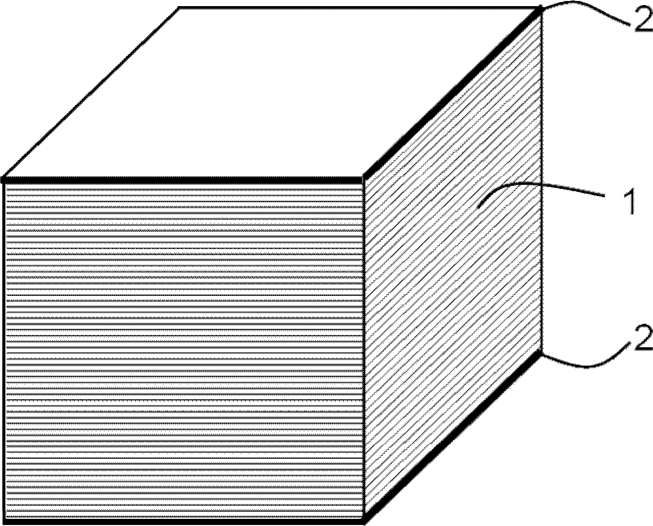
[0048] According to the preparation method of the present invention, a conventional cutting device such as a transverse shearing machine is first used to transversely cut the coiled amorphous alloy strip to form amorphous alloy sheets 1 with a predetermined thickness and the same shape. There are no particular limitations on the amorphous alloy strip and the method of obtaining the same.
[0049] Then, the obtained amorphous alloy sheets 1 with the same shape are sorted and laminated, and a fixed plate 2 with the same shape as the amorphous alloy sheet is placed on each of the two ends of the laminated body. Use compacting equipment to compact the amorphous alloy laminate. According to the requirements of the required lamination coefficient, the pressure is generally between 1 and 15 MPa. There is no requirement for the holding time, and the lamination coefficient is generally controlled at 0.85 to 0.98. between. In order to prevent the compacted amorphous alloy laminations f...
Embodiment 1
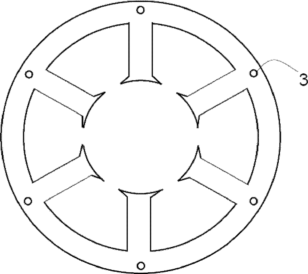
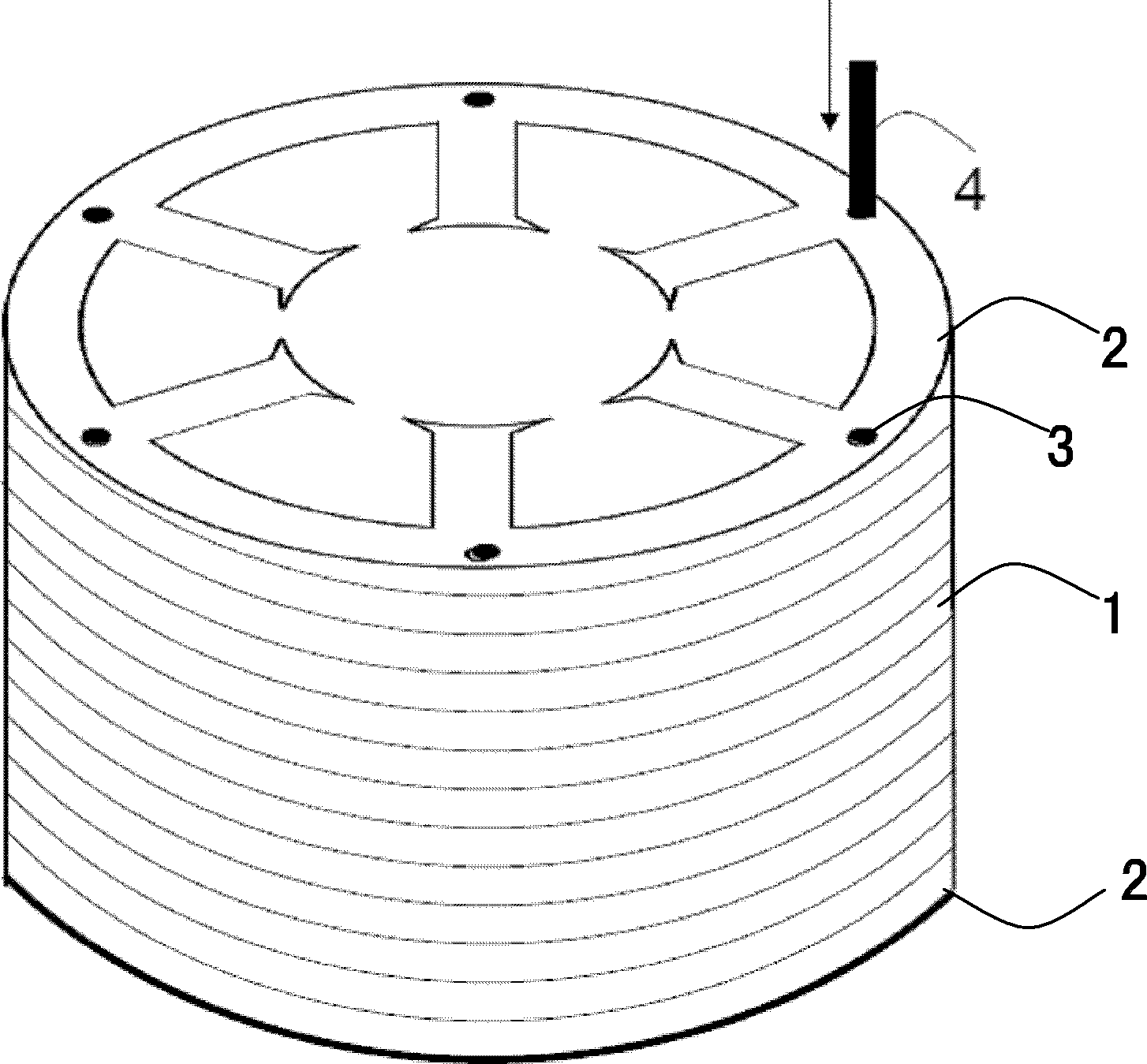
[0055] The nominal composition of the strip for making the amorphous alloy stator core is Fe 80 Si 9 B 11 (at.%), the thickness of the strip is 30±1μm, the width is 140mm, and the surface is flat and smooth. First use a cross-cutting machine to cut the amorphous strip into a square amorphous alloy sheet 1 with a length of 140mm, and then stack these square amorphous alloy sheets 1 into a high 100mm amorphous alloy laminate, and in the laminate A non-magnetic stainless steel plate 2 with the same shape as the amorphous alloy sheet 1 and a thickness of 1 mm is placed on the upper and lower sides, and after compaction and clamping (the lamination coefficient is 0.95) according to figure 2 The given drawings are cut by EDM. After cutting, the non-magnetic stainless steel strips 4 are inserted into the 6 small holes 3 of the amorphous laminate and welded and fixed with the non-magnetic stainless steel plates at both ends. Finally, the fixed non-magnetic The crystal alloy iron c...
Embodiment 2
[0065] The nominal composition of the strip for making the amorphous alloy stator core is Fe 80 Si 9 B 11 (at.%), the thickness of the strip is 30±1μm, the width is 140mm, and the surface is flat and smooth.
[0066] Firstly, the coiled amorphous alloy strip is treated with insulating coating, and the insulating coating is prepared by dipping and drying. Figure 5 is a schematic diagram of the insulation coating equipment. The insulating coating equipment has two dipping tanks 7 and 12, all made of PVC. The coating solution in the immersion tank 7 and the immersion tank 12 is 5% (wt.%) SiO 2 A mixture of nanopowder, 90% (wt.%) ethanol and 5% (wt.%) deionized water. The coiled amorphous alloy strip 5 first passes through the support shaft 6 and enters the immersion tank 7, removes excess dipping liquid through the scraper 8, and then passes through the heating tube 9 with dry hot air to dry. The drying temperature was 150°C. Then the amorphous strip is introduced into th...
PUM
| Property | Measurement | Unit |
|---|---|---|
| Magnetic flux density | aaaaa | aaaaa |
| Magnetic flux density | aaaaa | aaaaa |
| Thickness | aaaaa | aaaaa |
Abstract
Description
Claims
Application Information
 - R&D
- Intellectual Property
- Life Sciences
- Materials
- Tech Scout
- Unparalleled Data Quality
- Higher Quality Content
- 60% Fewer Hallucinations
Browse by: Latest US Patents, China's latest patents, Technical Efficacy Thesaurus, Application Domain, Technology Topic, Popular Technical Reports.
© 2025 PatSnap. All rights reserved.Legal|Privacy policy|Modern Slavery Act Transparency Statement|Sitemap|About US| Contact US: help@patsnap.com


