Back electromotive force harmonic compensation control method of permanent magnetic synchronous motor

A permanent magnet synchronous motor, back electromotive force technology, applied in electronic commutation motor control, motor control, motor generator control and other directions, can solve difficulties and other problems

Inactive Publication Date: 2012-10-17
DORNA TECH
View PDF3 Cites 8 Cited by
  • Summary
  • Abstract
  • Description
  • Claims
  • Application Information

AI Technical Summary

Problems solved by technology

Considering the complexity of the non-ideal distribution of the permanent magnet magnetic field of the permanent magnet synchronous motor rotor, it is difficult to establish a general mathematical model of the rotor harmonic magnetic field

Method used


Image

  • Back electromotive force harmonic compensation control method of permanent magnetic synchronous motor
  • Back electromotive force harmonic compensation control method of permanent magnetic synchronous motor
  • Back electromotive force harmonic compensation control method of permanent magnetic synchronous motor

Examples


Embodiment Construction

[0023] The principle and specific implementation of the present invention will be further described below in conjunction with the accompanying drawings.

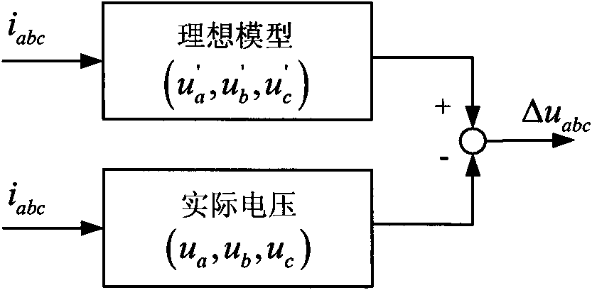
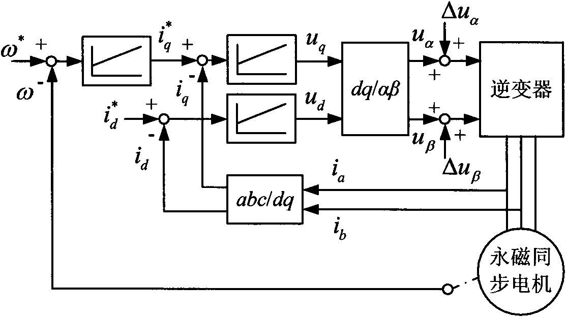
[0024] The permanent magnet synchronous motor back EMF harmonic compensation control method disclosed by the present invention is completed in two steps, which are respectively a method for extracting the harmonic back EMF of the permanent magnet synchronous motor and a compensation control method based on the harmonic back EMF component.

[0025] The steps of extracting the harmonic back EMF of the permanent magnet synchronous motor are as follows. In the control system, the phase voltage equation of the three-phase permanent magnet synchronous motor under ideal conditions is:

[0026] u a = Ri a + d ...


PUM


Abstract

The invention discloses a back electromotive force harmonic compensation control method of a permanent magnetic synchronous motor, wherein the method belongs to the motor control technology field. According to the compensation control method, on the basis of a stator voltage condition required for generating a perfect sine-wave current and a stable torque by a permanent magnetic synchronous motor, comparison with an actual terminal voltage of the motor is carried out by utilizing a stator voltage value obtained by an ideal motor model as a reference so as to obtain voltage distortion and the size of harmonic components, wherein the voltage distortion and harmonic components are caused by unideal characteristics of the motor; and compensation is carried out in a control loop to restrain the effects on the stator winding current and the torque by the back electromotive force harmonic component, thereby reducing operating losses of the motor and improving the stability of the motor torque control.

Description

technical field [0001] The invention relates to a counter electromotive force harmonic compensation control method of a permanent magnet synchronous motor, which belongs to the technical field of motor control. Background technique [0002] The premise of the vector control application of the permanent magnet synchronous motor is to assume that the motor is an ideal condition, not only the three-phase circuit of the stator is symmetrical, but also the magnetic field of the permanent magnet of the rotor is sinusoidally distributed in space. Due to manufacturing process problems, the actual motor cannot be completely ideal. For example, if the permanent magnet magnetic field loses its magnetism or contains harmonic components, it will induce harmonic back electromotive force in the stator winding, and irrational factors such as the cogging effect of the motor will also cause Harmonic counter electromotive force is induced in the stator winding, which will cause the motor to ge...

Claims


Application Information

Patent Timeline
Patent Type & Authority Applications(China)
IPC IPC(8): H02P21/00H02J3/01H02P25/022H02P29/50
CPCY02E40/40
Inventor 吕春松李社伟雷勤
Owner DORNA TECH
Why Eureka
Try Eureka