Catalytic cracking method and device

A catalytic cracking and catalyst technology, used in catalytic cracking, cracking, refining and cracking process treatment only in multi-stage series, etc. The effect of increasing liquid yield and decreasing yield

Inactive Publication Date: 2012-10-24
CHINA PETROLEUM & CHEM CORP +1
View PDF7 Cites 2 Cited by
  • Summary
  • Abstract
  • Description
  • Claims
  • Application Information

AI Technical Summary

Problems solved by technology

The disadvantage of this process is that although the residual activity of the gasoline spent catalyst is relatively high, there is still a certain gap compared with the regenerated catalyst.
This technology plans to add a regeneration inclined pipe and an air lift pipe, and set a catalyst cooler on the newly added regeneration inclined pipe. The cooled catalyst is mixed with the hot catalyst from the original regeneration inclined pipe, and the temperature is lower after mixing. The regenerant reacts with raw materials in contact. This technology can reduce the mixing temperature of the oil agent, increase the ratio of agent to oil, and improve product distribution. However, the cooling measures of the regenerant in this technology are slightly complicated and require more equipment.

Method used


Image

  • Catalytic cracking method and device
  • Catalytic cracking method and device
  • Catalytic cracking method and device

Examples


Embodiment

[0034] Embodiment 1 comparative example

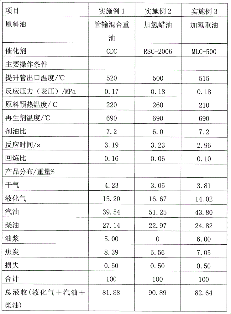
[0035] The test is carried out on a common riser catalytic cracking test device. The raw material oil is pipeline transported mixed heavy oil. The main properties are listed in Table 1. The processing capacity is 30 kg / day. It is 62, and the carbon content is 0.05w%. The main operating conditions, product distribution and main properties of the products of the riser reactor are listed in Table 2 and Table 3.

[0036] Embodiment 2 comparative example

[0037] By embodiment 1, the difference is that the raw material oil is hydrogenated wax oil, the main properties are listed in table 1, the processing capacity is 30 kg / day, and the catalyst used in the test is RSC-2006 industrial balancer, and the micro-reaction activity of the balance catalyst is 60 , the carbon content is 0.06w%. The main operating conditions, product distribution and main properties of the products of the riser reactor are listed in Table 2 and Table 3.

Embodiment 3

[0038] Embodiment 3 comparative example

[0039] By embodiment 1, the difference is that the raw material oil is a hydrogenated heavy oil, the main properties are listed in table 1, and the processing capacity is 30 kg / day, and the catalyst used in the test is an MLC-500 industrial balancer, and the micro-reaction activity of the equilibrium catalyst is 63, The carbon content is 0.03w%. The main operating conditions, product distribution and main properties of the products of the riser reactor are listed in Table 2 and Table 3.

Embodiment 4

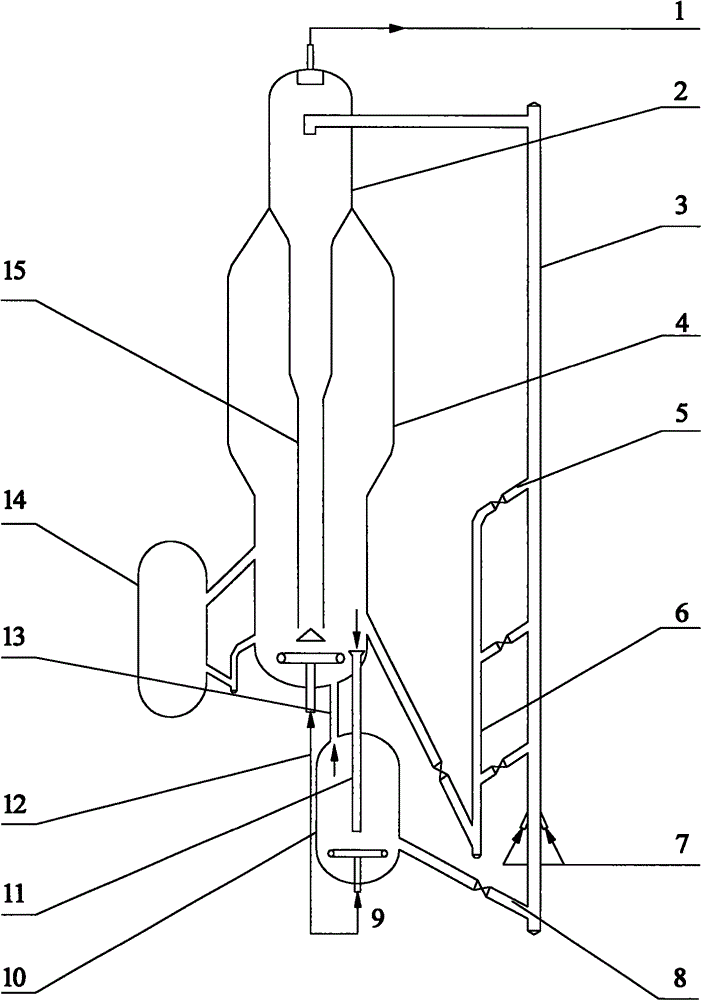
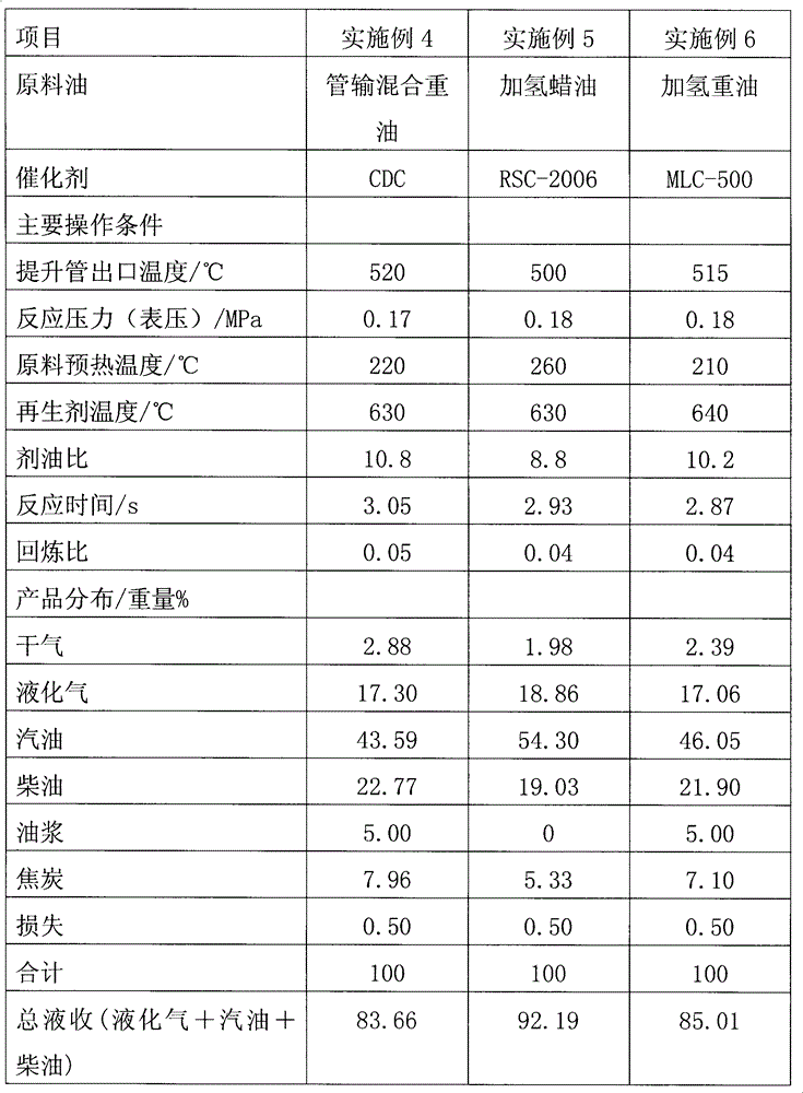
[0041] in such as figure 1 Test is carried out on the catalytic cracking test device shown, and processing capacity is 30 kilograms / day, and stock oil, catalyzer are identical with embodiment 1, and the main operating conditions of riser reactor, product distribution and the main character of product are listed in table 4 and table 5.


PUM


Abstract

The invention discloses a catalytic cracking method and device. The method is characterized by comprising the following steps: introducing raw oil into bottom of a riser reactor to contact and react with a catalyst from a catalyst heat exchanger; separating oil gas after the reaction from a coked catalyst; introducing separated reaction oil gas into a fractionating tower; carrying out steam stripping on the separated coked catalyst and sending the coked catalyst into a regenerator for regeneration; sending part of the regenerated catalyst into the riser reactor from different height positions of the riser; and carry out heat transfer on the other part of the regenerated catalyst by a heat exchanger and entering the other part of the regenerated catalyst into bottom of the riser reactor. The method of the invention can lower total yield of dry gas and coke by 0.5-1.5 percentage, increase total liquid yield of liquefied gas, gasoline and diesel by more than 1 percentage, and reduce gasoline olefin volume content by 5-15 percentage.

Description

technical field [0001] The invention belongs to the field of catalytic cracking of hydrocarbon oil in the absence of hydrogen, in particular to a catalytic cracking method and device in which catalysts enter a riser reactor in multiple stages. Background technique [0002] While paying attention to environmental protection, maximizing economic benefits is always the goal pursued by enterprises. However, lower dry gas, coke yield and high liquid yield have always been the fundamental means for catalytic cracking technology to improve economic benefits. In recent years, various domestic research institutes have carried out fruitful research on optimizing the anti-regeneration system of catalytic cracking units and improving the distribution of catalytic cracking products. [0003] The "X design" disclosed in US 5451313, UOP invented this new design in 1995. Its purpose is to increase the ratio of agent to oil and improve product distribution. It is characterized in that a cat...

Claims


Application Information

Patent Timeline
Patent Type & Authority Applications(China)
IPC IPC(8): C10G55/06C10G11/00
Inventor 闫鸿飞王龙延刘昱孟凡东樊麦跃陈曼桥乔立功汤海涛吴辰捷李秋芝
Owner CHINA PETROLEUM & CHEM CORP
Why Eureka
Try Eureka