Thinning heat conduction device with pipeless sealing structure and forming method of thinning heat conduction device

A sealing structure and thinning technology, applied in the direction of manufacturing tools, indirect heat exchangers, lighting and heating equipment, etc., can solve the problems of increased cost, increased defect rate, damage and scrapping of pipe body pressure breakage, etc., to simplify sealing components , The effect of reducing cost and defect rate, and best sealing quality

Inactive Publication Date: 2012-10-24
SUZHOU FORCECON ELECTRIC
View PDF4 Cites 4 Cited by
  • Summary
  • Abstract
  • Description
  • Claims
  • Application Information

AI Technical Summary

Problems solved by technology

[0004] However, the structural form of the existing heat conduction device mentioned in the previous paragraph has been found in practical applications. When the heat conduction device adopts a thinner design, many problems will arise in the sealing operation of the tube body. The pipe diameter potential of the pipe body must be relatively reduced (note: reduced to less than 6mm), so that the pipe body will affect the working efficiency and effect of filling the working fluid and vacuuming because of its too small pore diameter ; In addition, in the process of pressing and sealing the outer end of the tube body, the tube body is prone to be broken, damaged and scrapped because the tube diameter is too small; moreover, the tube body is relatively After all, it is a separately manufactured component, so it will inevitably cause problems and disadvantages such as increased costs in materials, assembly and processing, and increased defect rates during the production process.

Method used


Image

  • Thinning heat conduction device with pipeless sealing structure and forming method of thinning heat conduction device
  • Thinning heat conduction device with pipeless sealing structure and forming method of thinning heat conduction device
  • Thinning heat conduction device with pipeless sealing structure and forming method of thinning heat conduction device

Examples


Embodiment

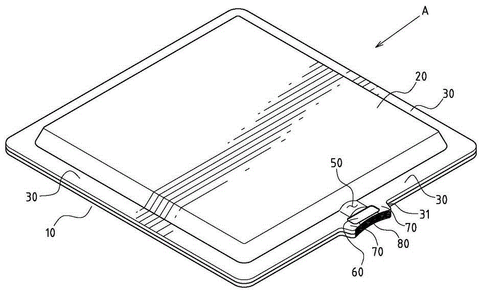
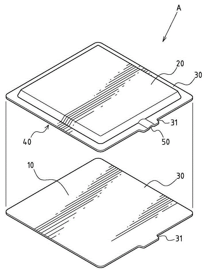
[0033] Example: see attached Figure 1~5 As shown, a thinned heat conduction device with a tubeless sealing structure, the thinned heat conduction device A with a tubeless sealed structure includes:

[0034] A substrate 10 is in the shape of a plate with a thickness and an area;

[0035] A cover plate 20 is in the shape of a plate body with a thickness and an area, and the shape of the cover plate 20 can be correspondingly attached to the surface of one side of the substrate 10;

[0036] The one-sided joint edge 30 is arranged in a plane-shaped corresponding abutment and joint-sealed form on the peripheral parts of the substrate 10 and the cover plate 20;

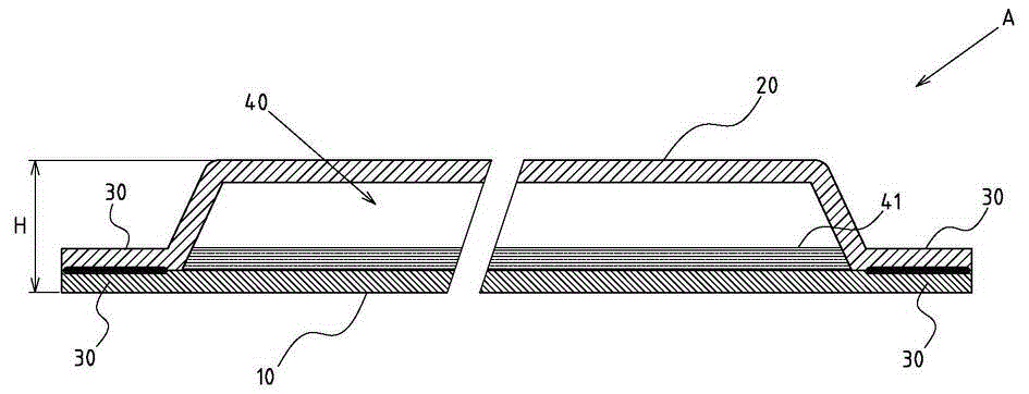
[0037] An internal space 40 is formed between the substrate 10 and the cover plate 20, and is surrounded by the planar joint edge 30. The internal space 40 is in a vacuum state and contains a working fluid 41 (such as image 3 shown);

[0038] A slit channel 50 is formed by leaving an unjoined part of one of the planar j...


PUM

PropertyMeasurementUnit
heightaaaaaaaaaa

Abstract

Disclosed are a thinning heat conduction device with a pipeless sealing structure and a forming method of the thinning heat conduction device. The thinning heat conduction device is characterized by comprising a base plate, a cover plate, a faceted joint side, an internal space, a gap channel, a press fit closing edge and spacing edges, the base plate and the cover plate are in the form of sheets and respectively have a thickness and an area, the faceted joint side is arranged on the peripheries of the base plate and the cover plate in a faceted correspondingly attached and joint sealing form, the internal space in an evacuated state is formed between the base plate and the cover plate and enclosed by the faceted joint side, working fluid is filled in the internal space, an unassembled position is reserved by the faceted joint side to form the gap channel, the section of the gap channel is in a gap form, the press fit closing edge is formed in a local section of the gap channel in a press fit form and blocks and closes the gap channel, and the spacing edges are formed between at least one side of the press fit closing edge and the outer side of the faceted joint side. Therefore, sealing components can be omitted and simplified, cost and defect rate are reduced, fine sealing quality is achieved, and the thinning heat conduction device has the advantages of fine structural strength and the like, and has practical progress.

Description

technical field [0001] The invention relates to a heat conduction device, in particular to an innovative design of a tubeless sealing structure of a thinned heat conduction device and a forming method thereof. Background technique [0002] General heat conduction devices such as heat pipes, heat plates, vapor chambers, etc., usually need to be filled with working fluid and vacuumed inside, so that when the heat conduction device is in operation, the internal heat transfer efficiency can be accelerated through the liquid and gas phase changes of the working fluid, so as to To achieve better heat transfer effect. [0003] If the existing heat conduction device is in the form of a hot plate or a vapor chamber, in order to facilitate the perfusion of the working fluid and the application of the vacuum process, a tube (also known as liquid injection) is usually installed at one point of the heat conduction device. Tube or vacuum tube) to use the tube body as a channel for fillin...

Claims


Application Information

Patent Timeline
Patent Type & Authority Applications(China)
IPC IPC(8): F28D15/02B23K28/02
Inventor 饶振奇何信威张中彦
Owner SUZHOU FORCECON ELECTRIC
Why Eureka
Try Eureka