Red light-emitting diode and preparation method

A technology of light-emitting diodes and red light, which is applied in the direction of electrical components, circuits, semiconductor devices, etc., can solve problems such as environmental hazards, increase the working voltage of light-emitting diodes, and reduce the working voltage of red light-emitting diodes, so as to increase efficiency and improve reverse Effect of current characteristics

Inactive Publication Date: 2012-10-24
天津中环新光科技有限公司 +1
View PDF0 Cites 3 Cited by
  • Summary
  • Abstract
  • Description
  • Claims
  • Application Information

AI Technical Summary

Problems solved by technology

However, as the number of distributed Bragg reflectors of AlAs and AlGaAs increases, the voltage applied to them will also increase. Therefore, it is not conducive to the reduction of the operating voltage of red light emitting diodes; in order to make the distributed Bragg reflector The voltage on the device is lowered. The usual practice is to adopt a heavy doping method in the aluminum arsenide and aluminum gallium arsenide materials that constitute the distributed Bragg reflector. However, the appearance of a large number of impurities will strengthen the absorption of photons, which is not conducive to light emission. In addition, the aluminum arsenide material is particularly sensitive to oxygen in the air medium. During use, a certain amount of aluminum arsenide will be oxidized to aluminum oxide, which is an insulating material with very poor conductivity. It will additionally increase the working voltage of the light-emitting diode, and it will also be accompanied by the generation of arsenic trioxide, which is harmful to the environment

Method used


Image

  • Red light-emitting diode and preparation method
  • Red light-emitting diode and preparation method

Examples


Embodiment Construction

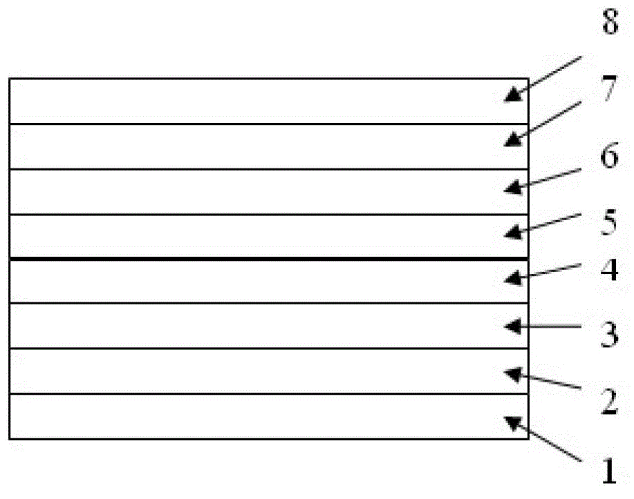
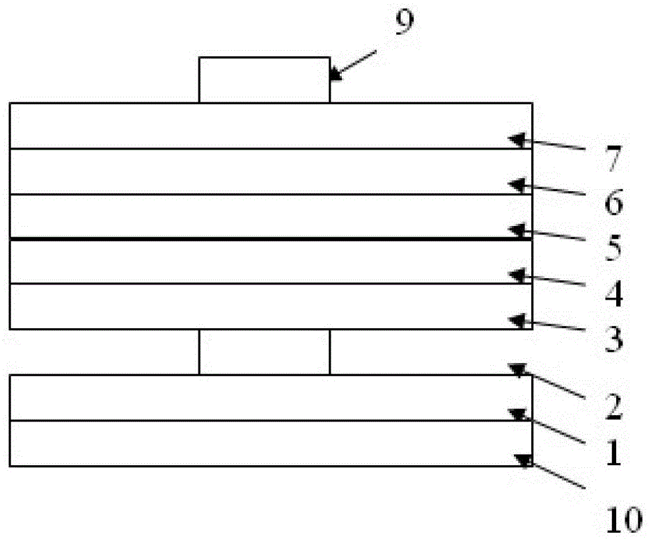
[0035] Such as figure 1 , figure 2 As shown, the present invention is provided with a gallium arsenide (GaAs) substrate 1, an aluminum arsenide (AlAs) base layer 2 is provided on the gallium arsenide (GaAs) substrate 1, and an aluminum arsenide (AlAs) base layer 2 is provided There is a distributed Bragg reflector 3, an n-type confinement layer 4 is arranged on the distributed Bragg reflector 3, and a multi-quantum well active region 5 constituting the core light-emitting region of the light-emitting diode is arranged on the n-type confinement layer 4, and the multi-quantum well active region 5 is arranged on the n-type confinement layer 4. A p-type confinement layer 6 is provided on the region 5; a p-type window layer 7 and a p-type capping layer 8 are provided on the p-type confinement layer 6, and a red light emitting diode structure is formed by interconnecting the above layer structures.

[0036]Among them, the above-mentioned distributed Bragg reflector 3 is made of al...


PUM


Abstract

The invention relates to a red light-emitting diode. The red light-emitting diode comprises a GaAs substrate; an AlAs base layer is arranged on the GaAs substrate; a distributed bragg reflector is arranged on the AlAs foundation base layer; a n type restriction layer is arranged on the distributed bragg reflector, a multiple quantum well active region forming a core light emitting region of the light-emitting diode is arranged on the n-type restriction layer, and a p type restriction layer is arranged on the multiple quantum well active region; a P type window layer and a P type cap layer are arranged on the p type restriction layer, and the structure of the red light-emitting diode is formed through the interconnection of the layer structures. For the red light-emitting diode, an air interlayer is formed between the aluminium gallium indium phosphide distributed bragg reflector and the GaAs substrate so that the light penetrating through the bragg reflector are effectively reflected out, and the efficiency of light emergence is improved; and one-step chemical treatment is carried out on a cutting surface of a chip in the corrosion process, semiconductor residues remained on the cutting surface of the chip are etched off, and the reverse current characteristic in the electric current-voltage characteristics of the chip of the light-emitting diode is improved.

Description

technical field [0001] The invention relates to a light-emitting diode, in particular to a red light-emitting diode with an aluminum arsenide (AlAs) base layer with an aluminum gallium indium phosphide distributed Bragg reflector (InAlGaP DBR) and a preparation method. Background technique [0002] Light-emitting diode (English lighting emitting diode, referred to as LED) is the core device in solid-state lighting. Because of its long life, high reliability, good energy saving, high electro-optical conversion efficiency and many other advantages, it is widely used. [0003] The technology of light-emitting diodes has been developed to the present, and the improvement of its brightness is basically based on the improvement of two efficiencies, namely: the improvement of internal quantum efficiency and the improvement of external quantum efficiency. Among them, the internal quantum efficiency mainly refers to the number of photons emitted from the internal light-emitting area ...

Claims


Application Information

Patent Timeline
Patent Type & Authority Applications(China)
IPC IPC(8): H01L33/10H01L33/30H01L33/00
Inventor 贾海强陈弘王晓晖宋京张荣勤丁国建
Owner 天津中环新光科技有限公司
Why Eureka
Try Eureka