Laminate for flexible wiring

A technology of flexible wiring and laminates, which is applied in the field of laminates for flexible wiring, and can solve problems such as inability to conduct with the other side, inability to increase wiring density, inability to conduct with through holes, etc., to achieve improved flexibility , high bending effect

Active Publication Date: 2012-10-24
JX NIPPON MINING & METALS CORP
View PDF8 Cites 3 Cited by
  • Summary
  • Abstract
  • Description
  • Claims
  • Application Information

AI Technical Summary

Problems solved by technology

[0016] In this case, since the thickness of the metal foil does not change, it is presumed that the bendability or flexibility is improved, but there is a disadvantage that extremely high plating is required because the plating area must be formed to be small and thin. Accuracy; in the case of densely arranged vias, the routing density cannot be increased
[0018] However, the problem in this case is that when conduction is conducted from one surface to the other surface through a via hole, the copper layer on one side conducts over a large area, while the copper layer on the other side is only connected to the copper layer. The extremely narrow area of ​​the partial cross-sectional area of ​​a layer
Moreover, when forming a through hole, if the copper layer does not form a smooth interface, there is a problem that it cannot conduct with the through hole, and thus cannot conduct with the other side.

Method used


Image

  • Laminate for flexible wiring
  • Laminate for flexible wiring
  • Laminate for flexible wiring

Examples


Embodiment 1

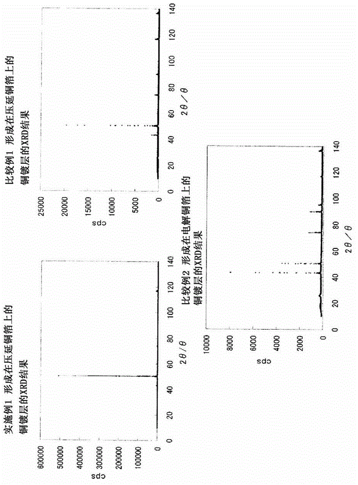
[0075] A 27.5 μm thick polyimide resin with an adhesive is used as an insulating resin substrate, and an 18 μm thick rolled sheet containing 0.02 mass % of Ag, 0.02 mass % of oxygen, and the balance of Cu and unavoidable impurities is used. Copper foil is used as copper foil. Rolled copper foil was arranged on one surface of the polyimide resin, and joined by thermocompression bonding at 180° C. for 60 minutes.

[0076] Next, under the above copper plating conditions, at 1A / dm 2 A current density of 10 μm thick copper was formed on a single-sided rolled copper foil glued to polyimide resin. In addition, the thickness of this plating layer was calculated by subtracting the known thickness of the resin film and copper foil from the thickness (total thickness) of the laminated body for flexible wirings of the whole, respectively.

[0077] A 1 cm x 1 cm square flexible wiring laminate sheet was cut out from the flexible wiring laminate sample sheet of Example 1 produced in this ...

Embodiment 2

[0085] A 27.5 μm thick polyimide resin with an adhesive is used as an insulating resin substrate, and an 18 μm thick rolled sheet containing 0.02 mass % of Ag, 0.02 mass % of oxygen, and the balance of Cu and unavoidable impurities is used. Copper foil is used as copper foil. Rolled copper foil was arranged on one surface of the polyimide resin, and joined by thermocompression bonding at 180° C. for 60 minutes.

[0086] Next, under the above copper plating conditions, at 4A / dm 2 A current density of 10 μm thick copper was formed on a single-sided rolled copper foil glued to polyimide resin. In addition, the thickness of this plating layer was calculated by subtracting the known thickness of the resin film and copper foil from the thickness (total thickness) of the laminated body for flexible wirings of the whole, respectively.

[0087] A 1 cm x 1 cm square flexible wiring laminate sheet was cut out from the flexible wiring laminate sample sheet of Example 2 produced in this ...


PUM

PropertyMeasurementUnit
thicknessaaaaaaaaaa
thicknessaaaaaaaaaa

Abstract

Disclosed is a laminate for flexible wiring, in which a copper plate is applied entirely or locally on a copper foil that is cladded on an insulating resin substrate, and which is characterized in that the ratio (A) of the area intensity of an X-ray peak in the X-ray diffraction on the surface of the copper plate (A = [(200) / {(111)+(200)+(220)+(311)}]100) is larger than 90. Also disclosed is a laminate for flexible wiring, in which a copper plate is applied entirely or locally on a copper foil that is cladded on an insulating resin substrate, and which has particularly high flexibility and enables the formation of fine patterns (highly dense patterns) of a wiring line.

Description

technical field [0001] The present invention relates to a laminate for flexible wiring in which copper plating is wholly or partially applied to copper foil bonded to an insulating resin substrate, and also relates to a laminate having particularly high flexibility and enabling fine patterning (higher density) of wiring laminates for flexible wiring. Background technique [0002] In recent years, with the development of miniaturized integration technology for mounting components such as semiconductor devices and various electronic chip components, printed wiring boards processed from laminates for flexible wiring for mounting these components require wiring Further refine the patterning and bendability of the laminate. [0003] Printed wiring boards based on organic materials are roughly divided into rigid copper-clad laminates (rigid) with epoxy glass substrates and phenolic paper substrates as constituent materials, and flexible laminates with polyimide substrates or poly...

Claims


Application Information

Patent Timeline
Patent Type & Authority Applications(China)
IPC IPC(8): C25D7/06B32B15/08C22C9/00H05K1/03H05K1/09
CPCC22C9/00H05K3/022B32B15/08C25D7/0607H05K1/09B32B5/00H05K2201/0355C25D5/02H05K2201/0154B32B15/20Y10T428/265Y10T428/31678C25D7/06H05K1/03
Inventor 山西敬亮新井英太三木敦史
Owner JX NIPPON MINING & METALS CORP
Why Eureka
Try Eureka