Benzene hydrogenation engineering heat resistant steel pipeline welding method
A welding method and heat-resistant steel technology, applied in welding equipment, metal processing equipment, manufacturing tools, etc., can solve the problems of complicated manufacturing process, high manufacturing cost, and inconvenient welding, so as to reduce construction cost, avoid residual stress, and design reasonable effect
- Summary
- Abstract
- Description
- Claims
- Application Information
AI Technical Summary
Problems solved by technology
Method used
Image
Examples
Embodiment 1
[0050] The heat-resistant steel pipeline welding method for benzene hydrogenation engineering of the present invention uses a TIG pulse welder to weld 12Cr2Mo brand pearlite heat-resistant steel by manual tungsten argon arc welding, and the supply state of the heat-resistant steel is 730-750°C Fire, is characterized in that comprising the steps of:
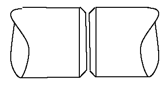
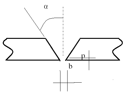
[0051] figure 1 It is a schematic diagram of the pipe-to-pipe butt joint groove structure according to the embodiment of the present invention, figure 2 It is a schematic diagram of the groove angle of the pipe-to-pipe butt joint of the embodiment of the present invention, and the pipe-to-pipe butt joint welding of the heat-resistant steel pipeline is performed.
[0052] a. Pipe section cutting and bevel processing
[0053] The pipe section is cut by plasma arc or flame, and the cut part is left with a machining allowance to remove the hardened layer and overheated metal; the diameter of the welded pipe section is ?32-273mm, an...
Embodiment 2
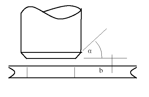
[0074] image 3 It is a schematic diagram of the groove angle of the pipe and the flange joint of the embodiment of the present invention, and the pipe and the flange joint of the heat-resistant steel pipeline are welded by the saddle joint. Plasma arc or mechanical cutting is used, and the oxidation pollution layer is removed mechanically at the welding groove and the near seam area; the branch pipe joints with a pipe wall thickness of more than 3mm are processed by machining groove α=45+5°, p=0, b= 2.0~2.4mm.
[0075] Figure 5 It is a schematic diagram of the protection device for the welding joint between the pipe and the flange in the embodiment of the present invention, and the protection device with the flange joint is provided with a blind plate on the flange and partial filling of argon in the pipe. Other technical features of this embodiment are the same as those of Embodiment 1.
PUM
| Property | Measurement | Unit |
|---|---|---|
| thickness | aaaaa | aaaaa |
Abstract
Description
Claims
Application Information
 - R&D
- Intellectual Property
- Life Sciences
- Materials
- Tech Scout
- Unparalleled Data Quality
- Higher Quality Content
- 60% Fewer Hallucinations
Browse by: Latest US Patents, China's latest patents, Technical Efficacy Thesaurus, Application Domain, Technology Topic, Popular Technical Reports.
© 2025 PatSnap. All rights reserved.Legal|Privacy policy|Modern Slavery Act Transparency Statement|Sitemap|About US| Contact US: help@patsnap.com


