
Electrolytic flotation equipment

An electrolytic air flotation and equipment technology, applied in the direction of flotation water/sewage treatment, etc., can solve the problems of affecting equipment promotion, reducing current efficiency, and high treatment costs, and achieving the effect of promoting biochemical treatment, prolonging residence time, and removing COD.

Active Publication Date: 2012-10-31
JIANGHUA WATER TREATMENT EQUIP PLANT JIANGSU
View PDF5 Cites 8 Cited by
  • Summary
  • Abstract
  • Description
  • Claims
  • Application Information

AI Technical Summary

Problems solved by technology

In addition, the traditional electrolysis method is not commonly used, mainly because the previous electrode has no breakthrough progress, coupled with design defects, the electrolytic air flotation electrode is easy to scale, consumes a lot of power, and the replacement of the electrode is complicated.
[0003] Insufficiency of traditional air flotation: the aeration tube or aeration head used in aeration air flotation may be clogged, and it is troublesome to replace after clogging. It is necessary to empty the water in the equipment or lift all the aeration tubes out of the water for replacement
Moreover, the failure of the aeration pipe under the water surface cannot be found in time, and it is generally repaired only after the air flotation effect is significantly reduced.
[0004] 1. The air utilization rate of aeration air floatation is very low, because the bubbles generated by the aeration head are large in size and rise fast, and the suspended solids in the water cannot be caught in time and have already surfaced.
[0005] 2. Dissolved air flotation has a complex structure and many supporting equipment, and the volume of bubbles produced is smaller than that of aeration method, but due to the addition of dissolved air links, the energy consumption is relatively large
[0006] 3. Because the traditional electrolysis method uses carbon steel or stainless steel as the electrode, the electrode will gradually dissolve, improve the chroma in the water, and the electrode surface will be passivated, reducing the current efficiency
[0007] 4. The electrodes of the traditional electrolysis method are fixed on the box body, and it is very troublesome to replace them. In addition, the electrodes are consumed quickly and need to be replaced frequently
[0008] 5. The traditional electrolysis method only uses the principle of electrolysis to produce gas, and does not optimize the electrode settings, resulting in low current efficiency and excessive energy consumption, which affects the promotion of equipment
In a preferred embodiment, a buffer water tank can be provided at the front end of the device of the present invention, and a magnetization module and a cavity can also be provided in the dispersion chamber, so as to achieve better degreasing effect and easier removal of scale on the electrode plate. Effect, this invention effectively overcomes the deficiencies of the prior art, but its electrodes are galvanized steel sheets, the electrodes will gradually dissolve, improve the chroma in water, the electrode surface will also scale, reduce the current efficiency, and its comb-shaped electrode group is fixed In the dispersion chamber, it is difficult to disassemble and replace, the electrode consumption is fast, and the processing cost is high

Method used


Image

  • Electrolytic flotation equipment
  • Electrolytic flotation equipment

Examples


Embodiment Construction

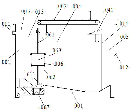
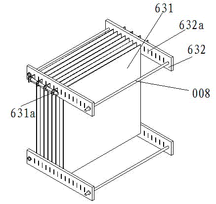
[0021] Such as figure 1 , 2 As shown, an electrolytic air flotation device includes a shell 001, the water inlet 011 and the water outlet 012 are respectively arranged on both sides of the shell 001, the slag scraping device 002 is set on the top of the shell 001, and the shell 001 is arranged at intervals in turn. The buffer baffle 013 and the overflow weir 014 divide the shell 001 into a buffer zone 003, a mixing zone 004, and a water outlet zone 005. The shell 001 above the end of the mixing zone 004 is provided with a corresponding slag scraping device 002. The slag discharge tank 041, the electrolytic generator 006 is provided at the bottom of the front end of the mixing zone 004, and the electrolytic generator 006 includes a guide rod 061, a mobile platform 062, and several electrode groups 063, and the guide rod 061 is vertical It is directly fixed on the bottom shell 001 at the front end of the mixing zone 004, the bottom end of the guide rod 061 is provided with a st...


PUM


Abstract

The invention discloses electrolytic flotation equipment. The electrolytic flotation equipment comprises a shell, wherein two sides of the shell are respectively provided with a water inlet and a water outlet, the top end of the shell is provided with a slag scraping device, buffering baffle plates and overflow weir plates are sequentially arranged in the shell at intervals to divide the shell into a buffering area, a mixing area and an effluent area, a slag discharging tank corresponding to the slag scraping device is arranged on the shell above the tail end of the mixing area, an electrolytic generator is arranged at the bottom of the front end of the mixing area and comprises a guide rod, a movable platform and a plurality of electrode groups, the guide rod is vertically fixed on the shell at the bottom of the front end of the mixing area, the bottom end of the guide rod is provided with a limiting stopper, the movable platform is movably sheathed on the guide rod, the electrode groups are fixed on the movable platform, electrodes can be very conveniently taken out of water for replacement, titanium-based oxidizing electrodes are used, and hypochlorite and hydroxyl free radicals are formed simultaneously when microbubbles are formed so as to effectively reduce the COD (Chemical Oxygen Demand), improve the B / C ratio and be beneficial to the follow-up biological treatment.

Description

technical field [0001] The invention relates to electrolytic air flotation equipment in the field of air flotation equipment, which is used for removing suspended matter and particulate matter in liquid. Background technique [0002] The air flotation equipment mainly uses highly dispersed micro-bubbles as the carrier to adhere to the hydrophobic-based objects in the wastewater, so that the small bubbles and objects are regarded as a whole, and their overall density is lower than that of water to float to the water surface, thereby realizing solid-liquid or liquid-liquid process of separation. In water treatment, the air flotation method can be used in occasions where the sedimentation method is not applicable, to separate suspended solids whose specific gravity is close to water and difficult to settle, such as oil, fiber, algae, etc., and can also be used to concentrate activated sludge. There are two commonly used methods for generating microbubbles: aerated air flotatio...

Claims


Application Information

Patent Timeline
Patent Type & Authority Applications(China)
IPC IPC(8): C02F1/465
Inventor 郑巍
Owner JIANGHUA WATER TREATMENT EQUIP PLANT JIANGSU
Learn More