
Efficient nitrogen and phosphorus removal method for sewage properties-classified treatment in highway service area

A technology for quality-based treatment, nitrogen and phosphorus removal, applied in water/sewage multi-stage treatment, water/sludge/sewage treatment, chemical instruments and methods, etc., can solve the problem of large footprint and large carbon source dosage , high chemical costs and other issues, to achieve the effect of reducing carbon dioxide, reducing aeration, and high nitrogen removal efficiency

Inactive Publication Date: 2012-10-31
JIANGSU PROVINCIAL ACAD OF ENVIRONMENTAL SCI
View PDF4 Cites 13 Cited by
  • Summary
  • Abstract
  • Description
  • Claims
  • Application Information

AI Technical Summary

Problems solved by technology

However, adding additional carbon sources requires higher chemical costs. For high-nitrogen and phosphorus wastewater in expressway service areas, a large amount of carbon sources is required, which significantly increases the treatment cost.
In addition, adding ecological treatment processes such as constructed wetlands after conventional treatment processes can also increase the removal rate of total nitrogen, but due to the limited nitrogen required for wetland plant growth, the removal ability of TN is not strong, and wetlands require a large area area, not an optimal solution

Method used


Image

  • Efficient nitrogen and phosphorus removal method for sewage properties-classified treatment in highway service area
  • Efficient nitrogen and phosphorus removal method for sewage properties-classified treatment in highway service area

Examples


Embodiment 1

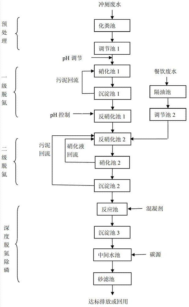
[0036] The wastewater from the expressway service area is collected separately from toilet flushing wastewater, catering wastewater and other wastewater. The toilet flushing wastewater enters the septic tank, and the septic tank wastewater flows into the regulating tank 1 by itself, while other wastewater also enters the regulating tank 1, with a residence time of 24h. The catering wastewater enters the conditioning tank 2 through the grease trap for a stay time of 24h. The wastewater from the regulating tank 1 enters the nitrification tank 1 for a residence time of 6h, and the dissolved oxygen is controlled to be 1.0mg / L. The wastewater from the nitrification tank 1 enters the sedimentation tank 1 for precipitation, the sludge in the sedimentation tank 1 returns to the nitrification tank 1, and the supernatant enters the denitrification tank 1. Add NaOH and NaHCO in denitrification tank 1 3 Adjust the pH to 8.2, fill the denitrification tank 1 with elastic fillers, and an ana...

Embodiment 2

[0041] The wastewater from the expressway service area is collected separately from toilet flushing wastewater, catering wastewater and other wastewater. The toilet flushing wastewater enters the septic tank, the septic tank wastewater flows into the regulating tank 1 by itself, and the catering wastewater enters the regulating tank 2 through the grease trap. At the same time, other wastewater also enters the regulating tank 2. The wastewater from the regulating tank 1 enters the nitrification tank 1, and the dissolved oxygen is controlled at 3.0 mg / L to fully oxidize the ammonia nitrogen into nitrate. The wastewater from the nitrification tank 1 enters the sedimentation tank 1, the sludge of the sedimentation tank 1 returns to the nitrification tank 1, and the supernatant enters the denitrification tank 1. NaOH is added to the denitrification tank 1 to adjust the pH, and the effluent from the denitrification tank 1 enters the denitrification tank 2. Both denitrification tank ...

Embodiment 3

[0046] The wastewater from the expressway service area is collected separately from toilet flushing wastewater, catering wastewater and other wastewater. The toilet flushing wastewater enters the septic tank, the septic tank wastewater flows into the regulating tank 1 by itself, and the catering wastewater enters the regulating tank 2 through the grease trap. At the same time, other wastewater also enters the regulating tank 2. The effluent from the regulating tank 2 enters the denitrification tank 1 and the denitrification tank 2 at the ratio of 70% and 30% respectively. Among them, the wastewater from the regulating tank 1 enters the nitrification tank 1, and the dissolved oxygen is controlled to be 2.0 mg / L, and the residence time is 6 hours to partially oxidize the ammonia nitrogen into nitrate. The wastewater from the nitrification tank 1 enters the sedimentation tank 1, the sludge of the sedimentation tank 1 returns to the nitrification tank 1, and the supernatant enters ...


PUM


Abstract

The invention discloses an efficient nitrogen and phosphorus removal method for sewage properties-classified treatment in a highway service area. The efficient nitrogen and phosphorus removal method includes that toilet flushing sewage in the highway service area flows into a septic tank to be treated, the sewage in the septic tank sequentially flows through an adjusting tank (1), a nitration tank (1), a settling tank (1), a denitrification tank (1), a denitrification tank (2), a nitration tank (2) and a settling tank (2), and when effluent in the settling tank (2) reaches the standard, the effluent is discharged; simultaneously, catering sewage flows into an oil separation tank to be treated, and the sewage in the oil separation tank flows into an adjusting tank (2); the catering sewage and the toilet flushing sewage share the denitrification tank (1) and the denitrification tank (2), and the treatment method of the catering sewage flowing into the denitrification tank (1) or the denitrification tank (2) is identical to that of the toilet flushing sewage flowing into the denitrification tank (1) or the denitrification tank (2); simultaneously, other sewage flows into the adjusting tank (1) or the adjusting tank (2); if the other sewage flows into the adjusting tank (1), the treatment method of the other sewage flowing into the adjusting tank (1) is identical to that of the toilet flushing sewage flowing into the adjusting tank (1); and if the other sewage flows into the adjusting tank (2), the treatment method of the other sewage flowing into the adjusting tank (2) is identical to that of the catering sewage flowing into the adjusting tank (2).

Description

Technical field [0001] The invention belongs to the technical field of environmental protection, and relates to a method for treating sewage in an expressway service area. The method is also suitable for sewage treatment and high-efficiency denitrification and dephosphorization of other catering, tourism, livestock and poultry breeding industries. Background technique [0002] The condition of highway construction reflects the degree of traffic development of a country and region, and even the overall level of economic development. The construction of expressways in China started relatively late. The earliest expressway to be constructed was the Shen-Da Expressway, which was completed in 1990. However, the development of China's expressways is very fast. By the end of 2010, China's expressway mileage reached 74,000 kilometers, ranking second in the world. The rapid development of expressways has also brought corresponding environmental problems. Among them, sewage treatment in ...

Claims


Application Information

Patent Timeline
IPC IPC(8): C02F9/14
Inventor 陆继来涂勇张敏健叶阳阳刘伟京吴海锁
Owner JIANGSU PROVINCIAL ACAD OF ENVIRONMENTAL SCI
Learn More