Coupled power generating system using solar thermal collector assisted coal-fired unit

A solar collector and power generation system technology, applied in the direction of solar thermal power generation, the use of solar energy to generate mechanical power, solar thermal devices, etc. Conducive to sustainable development, ensuring power supply stability and optimizing energy structure

Inactive Publication Date: 2012-10-31
NORTH CHINA ELECTRIC POWER UNIV (BAODING)
View PDF5 Cites 18 Cited by
  • Summary
  • Abstract
  • Description
  • Claims
  • Application Information

AI Technical Summary

Problems solved by technology

When the heat collection temperature of the system is higher than 400°C, its heat collection efficiency is reduced, for example, when the solar radiation value is 800W/m 2, , the heat collection efficiency at 500°C is about 22.5% lower than that at 250°C
Constrained by the conditions of low geometric concentration ratio and low heat collection temperature, th

Method used


Image

  • Coupled power generating system using solar thermal collector assisted coal-fired unit
  • Coupled power generating system using solar thermal collector assisted coal-fired unit
  • Coupled power generating system using solar thermal collector assisted coal-fired unit

Examples


Embodiment Construction

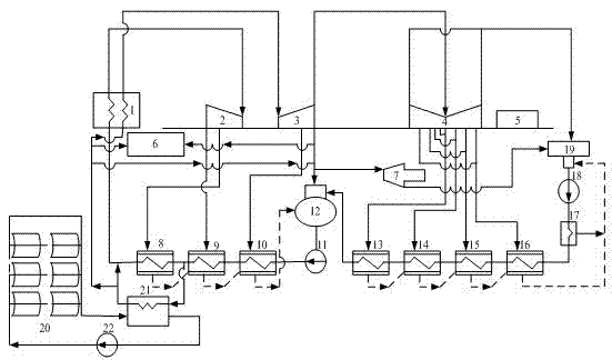
[0018] figure 1 As the first embodiment of the present invention, the coupled power generation system consists of a coal-fired boiler 1, a steam turbine, a generator 5, a heater, a solar collector field (20), a thermal oil heat exchanger 21, an auxiliary steam header 6, Feedwater pump 11, deaerator 12, condenser 19, condensate pump 18, etc., among which the solar heat collector field (20) 20 is formed by connecting glass-covered vacuum trough solar heat collectors in series and parallel. The system flow is: the condensed water flowing out from the condenser 19 passes through the condensed water pump 18 and the series-connected shaft seal heater 17, the first stage low pressure heater 16, the second stage low pressure heater 15, and the third stage low pressure heater 14 1. After the fourth-stage low-pressure heater 13 carries out the initial temperature and pressure increase, it enters the deaerator 12 to remove oxygen, and then passes through the feed water pump 11 to increa...


PUM


Abstract

The invention provides a coupled power generating system using a solar thermal collector assisted coal-fired unit. The system comprises a coal-fired boiler power generating system, a solar thermal collector field, a circulating pump and a hot oil heat exchanger, wherein the coal-fired boiler power generating system comprises a generator and a condenser, a condensate pump, multiple stages of low-pressure heaters, a deaerator, a feed pump, multiple stages of high-pressure heaters, a coal-fired boiler and a steam turbine, which are connected in series in sequence; the steam turbine drives the generator and the steam exhausted by the steam turbine enters the condenser; the solar thermal collector field, the circulating pump and an oil chamber of the heat exchanger are connected to form a circulation loop; and a part of feed water from the inlet end of the high-pressure heater at one stage is sent to the high-pressure heater at the next stage, the cold reheat steam inlet or the feed pump steam turbine inlet after being heated by the heat exchanger. The system has the following beneficial effects: as the solar thermal collector field and the traditional coal-fired boiler power generating system are organically bonded, the coal consumption of the power plants is greatly reduced and the environmental pollution of the power generating system is reduced while the power supply stability is ensured.

Description

technical field [0001] The invention relates to a coupled power generation system using a glass cover vacuum trough solar heat collector to assist a coal-fired unit, and belongs to the technical field of power generation. Background technique [0002] At present, thermal power generation still occupies a dominant position in the existing power supply system. The thermal power generation system has the advantages of mature technology and convenient adjustment. The disadvantage is that it needs to consume a large amount of coal resources, and the energy utilization rate is low (the thermal efficiency is about 40%). The emission of harmful gases such as carbon dioxide is large, causing serious pollution to the environment. [0003] The start-up boiler of a thermal power plant is generally built in a new power plant and the first unit. Its purpose is to supply steam to the starting unit during the start-up process of the first unit, and when the unit restarts due to failure, it ...

Claims


Application Information

Patent Timeline
IPC IPC(8): F03G6/06F01D15/10F22D1/00F24J2/04
CPCY02E10/46Y02E10/44
Inventor 韩中合王继选李恒凡刘小贞
Owner NORTH CHINA ELECTRIC POWER UNIV (BAODING)
Why Eureka
Try Eureka