Multilayer heat insulation barrel device and production method thereof

A technology of multi-layer heat insulation and manufacturing method, which is applied in the preparation of heat-insulation cylinders and the field of multi-layer heat-insulation cylinder devices, which can solve the problems of hollow cylinders such as easy damage, rising use costs, and general heat preservation effects, and achieve cost reduction , prolong the service life, accelerate the effect of heat loss

Active Publication Date: 2012-10-31
DALIAN LONGTIAN TECH
View PDF5 Cites 13 Cited by
  • Summary
  • Abstract
  • Description
  • Claims
  • Application Information

AI Technical Summary

Problems solved by technology

The thermal insulation effect of the carbon felt insulation cylinder prepared by the former method is average, and it occupies a large space and has a short service life; while the solidified carbon felt insulation cylinder prepared by the latter method must be completed on a mold. When the number of molds is limited, It will prolong the production time, and there are problems such as high production cost, and the hollow cylinder is easy to be damaged during storage and transportation. Moreover, this insulation cylinder is a whole. If a certain part is damaged, it needs to be replaced as a whole, resulting in an increase in the cost of use.

Method used


Image

  • Multilayer heat insulation barrel device and production method thereof
  • Multilayer heat insulation barrel device and production method thereof
  • Multilayer heat insulation barrel device and production method thereof

Examples


Embodiment 1

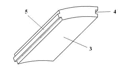
[0027] The first step is to prepare the slat unit and the sliding member: according to the required size, determine the size and radian of the multi-layer insulation tube slat unit 3 and the sliding member 2; design and prepare the slat unit 3 and the sliding member according to the determined size and radian The corresponding mold of component 2; infiltrate the carbon fiber felt into the curing agent with a resin mass fraction of 10% resin-alcohol solution until the carbon felt fully absorbs the curing agent, take it out and place it at room temperature until the curing agent stops dripping, and then put it in In a mold with a radian of 2π / n (n is the number of slat units, generally 6-8), pressurize 1.2×10 at 60°C 4 Pa, after curing for 3 hours, raise the temperature to 140°C for deep curing for 8 hours, put it into a high-temperature furnace for carbonization treatment at 1200°C for 48 hours after curing, and finally put it in a vacuum graphite sintering furnace for graphitiz...

Embodiment 2

[0033] The second step is assembled with embodiment 1.

[0034] Example 3

[0035] structured as Figure 5 The specific implementation steps of the preparation method of the shown multi-layer heat insulation cylinder device are as follows:

Embodiment 3

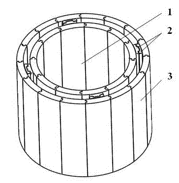
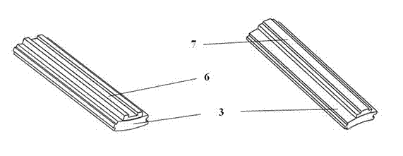
[0037] The second step of assembly: install four chute 6 symmetrically and fixedly on the inner wall of the heat insulation cylinder in the inner layer, and install four guide strips 7 symmetrically on the outer wall of the heat insulation cylinder in the middle layer, connect the chute 6 and the guide strip 7, and the inner layer The sliding between the heat insulation cylinder 1 and the middle layer heat insulation cylinder 8 can be realized by the relative sliding of the chute 6 and the guide bar 7; Cylinder 9 adopts an integral heat insulation cylinder, and the relative sliding between the middle layer heat insulation cylinder and the outer layer heat insulation cylinder is realized by a smooth wall (such as Figure 5 shown).


PUM


Abstract

The invention belongs to the technical field of heat insulation and heat preservation, and more particularly relates to a multilayer heat insulation barrel. The multilayer heat insulation barrel is formed by at least sleeving two single-layer heat insulation barrels inside and outside in a relative sliding manner, wherein the heat insulation barrel at the innermost layer is a slat-type heat insulation barrel movably spliced by slat units, and the other heat insulation barrels are slat-type heat insulation barrels movably spliced by the slat units or integral heat insulation barrels. The multilayer heat insulation barrel device disclosed by the invention is simple to operate and easy to implement and can be used for producing a solidified felt heat insulation barrel which is good in heat insulation effect, long in service life, low in preparation cost, controllable in heat preservation effect and convenient to store and transport.

Description

technical field [0001] The invention belongs to the technical field of heat insulation, and in particular relates to a multi-layer heat insulation cylinder device for heat insulation and heat insulation. In addition, the invention also relates to a preparation method of the heat insulation cylinder. Background technique [0002] Carbon fiber felt is a blank material for preparing carbon / carbon composite structural materials and carbon / carbon composite thermal insulation materials. Carbon / carbon composite insulation materials are widely used in thermal insulation due to their excellent properties such as small thermal conductivity, low heat capacity, low density, small linear expansion coefficient, high temperature resistance, strong thermal shock resistance, strong chemical corrosion resistance, high purity and no pollution. Aerospace, communication optical fiber, new energy, high-performance ceramic preparation, crystal growth fields, and with the development of new energy ...

Claims


Application Information

Patent Timeline
Patent Type & Authority Applications(China)
IPC IPC(8): F27D1/00C04B35/83
Inventor 谭毅施伟战丽姝
Owner DALIAN LONGTIAN TECH
Why Eureka
Try Eureka