Absorption oil-gas recycling system and absorption oil-gas recycling process

A recycling and adsorption technology, applied in the separation of dispersed particles, chemical instruments and methods, separation methods, etc., can solve the problems of high environmental requirements, high power consumption, high cost, and achieve significant energy saving and environmental protection, easy to reuse, significant effect

Active Publication Date: 2012-11-07
BAY ENVIRONMENTAL TECH BEIJING
View PDF3 Cites 12 Cited by
  • Summary
  • Abstract
  • Description
  • Claims
  • Application Information

AI Technical Summary

Problems solved by technology

The system adopts the technical scheme of three-stage condensation, intermediate pressurization and tail gas recovery, so that the volatilized oil gas can be recovered, and the energy saving effect is better. However, the multi-stage condensation setting of the system inevitably has large power consumption, Due to the complex distribution of equipment, high environmental requirements and high cost, it is not suitable for popularization and application, especially in the large-scale recovery of crude oil and gas.

Method used


Image

  • Absorption oil-gas recycling system and absorption oil-gas recycling process

Examples


Embodiment 1

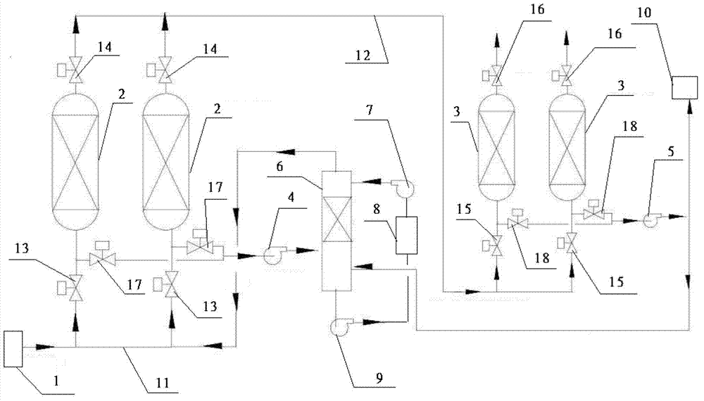
[0047] Such as figure 1 As shown, the adsorption oil and gas recovery treatment system of the present invention includes a control system (not shown in the figure) and an oil and gas input system 1 controlled by the control system, an adsorption device, a desorption device, an absorption device and a storage device connected to each other; The adsorption device is connected with the oil and gas input system 1; wherein:

[0048] The absorption device includes an absorption tower 6 and an absorbent supply device connected to the absorption tower 6, and the absorbent supply device includes an absorbent delivery pump 7 and an absorbent storage tank 8 connected to each other;

[0049] The desorption device is a secondary desorption device, including a first-stage desorption vacuum pump 4 and a second-stage desorption vacuum pump 5 connected to the absorption tower 6;

[0050] The storage device includes a liquid storage device and a gas storage device 10, the liquid storage device...

Embodiment 2

[0083] Such as figure 1 As shown, the setting and distribution of an adsorption oil gas recovery treatment system are the same as in Embodiment 1.

[0084] Applying the adsorption type oil gas recovery treatment system of the present invention to carry out crude oil gas recovery treatment process is the same as embodiment 1, except the following steps:

[0085] In step (2), the concentration of the effluent is measured to reach 30g / m by analyzing the online concentration analyzer 3 , alternately replace the first-stage adsorption tower 2 and / or the second-stage adsorption tower 3 for adsorption; the specific surface of the adsorbent activated carbon is 240,000m 2 / kg;

[0086] In step (3), the vacuum degree during the desorption of the first-stage desorption vacuum pump 4 and the second-stage desorption vacuum pump 5 is 90kpa;

[0087] In step (4), the absorbent is gasoline, and the flow rate of gasoline circulated through the absorbent delivery pump 7 is 80m 3 / h.

[008...

Embodiment 3

[0090] Such as figure 1 As shown, the setting and distribution of an adsorption oil gas recovery treatment system are the same as in Embodiment 1.

[0091] Applying the adsorption type oil gas recovery treatment system of the present invention to carry out crude oil gas recovery treatment process is the same as embodiment 1, except the following steps:

[0092] In step (2), the concentration of the effluent is measured to reach 25g / m by analyzing the online concentration analyzer 3 , alternately replace the first-stage adsorption tower 2 and / or the second-stage adsorption tower 3 for adsorption; the specific surface of the adsorbent activated carbon is 200,000m 2 / kg;

[0093] In step (3), the vacuum degree during desorption of the first-stage desorption vacuum pump 4 and the second-stage desorption vacuum pump 5 is 85kpa;

[0094] In step (4), the absorbent is diesel oil, and the flow rate of the diesel oil to be circulated through the absorbent delivery pump 7 is 50m 3 / ...


PUM


Abstract

The invention relates to an absorption oil-gas recycling system and an absorption oil-gas recycling process. The system comprises an absorption device, a desorption device, an intake device and a storage device, which are connected with one another. The absorption device and the desorption device are more first-staged. By the absorption oil-gas recycling system, the recycling process by combining multistage absorption and desorption is achieved, the problems of pollution and waste of hydrocarbon components in oil and gas are solved, external environment is protected effectively, and energy is utilized efficiently and economically. The absorption oil-gas recycling system is suitable for popularization and application in related oil-gas recycling fields, especially suitable for fields such as lean oil recycling and reusing and crude oil-gas recycling and reusing.

Description

technical field [0001] The invention relates to an oil gas recovery treatment system and a recovery treatment process thereof, in particular to an adsorption type oil gas recovery treatment system and a recovery treatment process thereof. Background technique [0002] At present, in the process of crude oil extraction, processing and application, oil and gas are basically produced. The escape or incineration of these oil and gas mainly has two effects. On the one hand, it causes a large amount of light oil energy waste, and on the other hand, it causes environmental pollution. It is the air pollution that seriously affects the health of the relevant people. Therefore, it is urgent to research and develop technologies that can effectively recover these oil gases. [0003] In the prior art, the patent CN201626827U provides a condensation oil vapor recovery system, which can be applied to the recovery of volatile oil vapor with low carbon content such as crude oil and gasoline ...

Claims


Application Information

Patent Timeline
Patent Type & Authority Applications(China)
IPC IPC(8): B01D53/04
Inventor 巍巍
Owner BAY ENVIRONMENTAL TECH BEIJING
Why Eureka
Try Eureka