
Method for welding carbon steel medium plate

A welding method and technology for thick plates, applied in welding equipment, arc welding equipment, manufacturing tools, etc., can solve problems such as low production efficiency, poor quality, and poor realizability, and achieve strong practicability, simple operation, and high economy Effect

Active Publication Date: 2015-04-15
CRRC CHANGCHUN RAILWAY VEHICLES CO LTD
View PDF2 Cites 0 Cited by
  • Summary
  • Abstract
  • Description
  • Claims
  • Application Information

AI Technical Summary

Problems solved by technology

[0006] In order to solve the technical problems such as limited position, poor quality, serious deformation, low production efficiency, and poor realizability in the existing medium and thick plate welding technology, the present invention proposes a high-quality and efficient carbon steel medium and thick plate welding method, Especially suitable for plate welding with a thickness not greater than 20mm

Method used


Image

  • Method for welding carbon steel medium plate
  • Method for welding carbon steel medium plate
  • Method for welding carbon steel medium plate

Examples


Embodiment 1

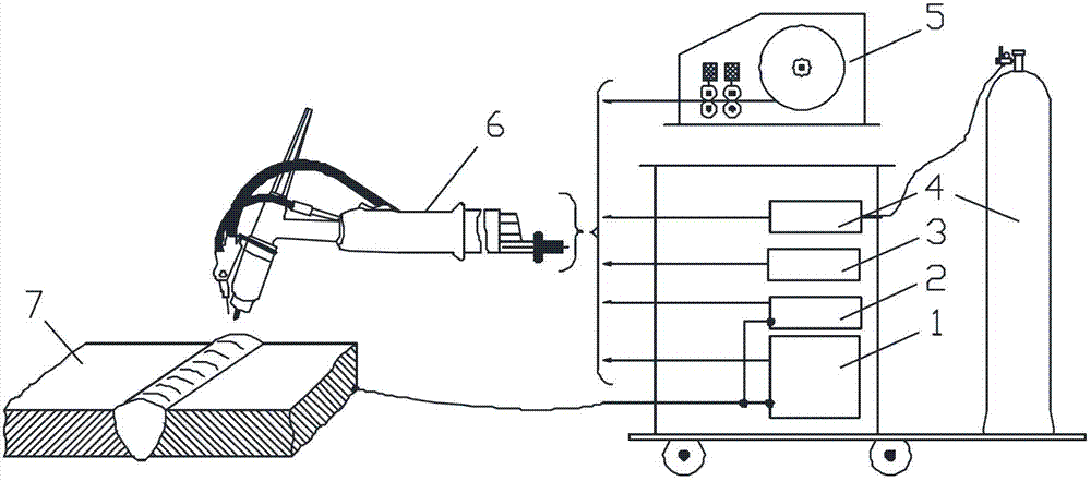
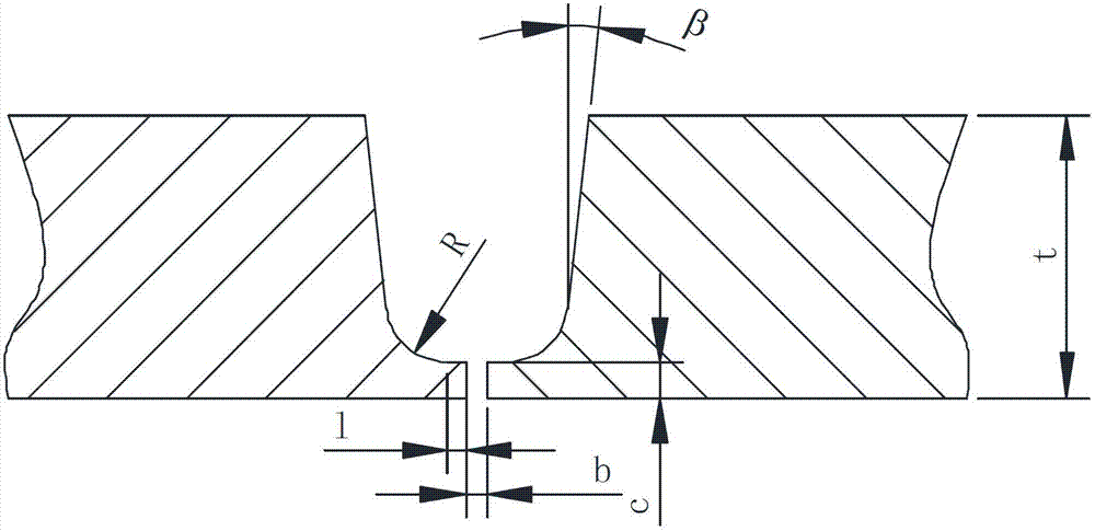
[0021] Example 1: Combining figure 1 , figure 2 and image 3 Describe this embodiment. The welding system used in this embodiment consists of a welding power source 1, a DC heating wire power source 2, a water cooling device 3, an air supply device 4, a dynamic wire feeder 5, and a set of wire feeding, gas supply and water cooling functions. The welding gun consists of 6 components. The welding base metal 7 is Q690D high-strength tempered steel with a thickness of t=16mm. Groove is figure 2 For the U-shaped groove shown, the thickness of the blunt side is C=1.5mm, the parallel length l=1.0mm, the chamfer R=3.5°, and the single-side groove angle β=6°. The filler material is ER100S-G disc-shaped welding wire with a diameter of 1.0mm. The tungsten electrode is a cerium tungsten electrode with a diameter of 3.2mm, and the grinding angle range of the tip is 25~30°. The nozzle is No. 8 ceramic nozzle. When the workpieces to be welded are spot-fixed, the self-fluxing method ...

Embodiment 2

[0022] Embodiment 2: The difference between this embodiment and Embodiment 1 is that the Figure 4 The double-pass weaving welding method in which the fusion effect of the side wall can be more easily guaranteed uses the same working parameters as the first embodiment.

Embodiment 3

[0023] Embodiment 3: The difference between this embodiment and Embodiment 1 is that the Figure 5 Single swing and double swing composite welding methods. Among them, the first layer (root welding) and the second layer at the bottom of the weld adopt the single-channel swing operation mode, and the third layer and above to the cover surface adopt the double-channel swing mode, and the working parameters used are the same as those in the first embodiment.


PUM

PropertyMeasurementUnit
thicknessaaaaaaaaaa
diameteraaaaaaaaaa
diameteraaaaaaaaaa

Abstract

The invention discloses a method for welding a carbon steel medium plate, and belongs to the technical field of non-melt electrode arc welding and electric arc welding smelting. The method is used for welding by the aid of a TT (tip tungsten inert gas welding) system, and is particularly suitable for welding medium plates with the thicknesses not larger than 20mm. A workpiece to be welded is provided with a U-shaped groove, the angle of a single edge of the workpiece to be welded ranges from 5 degrees to 7 degrees, the thickness of a truncated edge ranges from 1.5mm to 2.0mm, a self-melting mode is adopted when the workpiece to be welded is in tack welding, and assembly gaps are controlled to range from 0mm to 1.0mm; and a swing operation mode is adopted in a welding process, and two sides of the grooves are heated by electric arcs. The method has the advantages that requirements on the machining precision of the groove are low, splashing is prevented in the welding process, an excellent side wall welding effect can be guaranteed, section areas of weld joints are small, deposited metal at the weld joints is little, welding efficiency is high, the method is particularly applicable to welding medium plate structures with high quality requirements for important carrying components and is simple in operation, and automation is realized easily.

Description

technical field [0001] The invention belongs to the technical field of non-melting electrode arc welding and arc smelting, and relates to a welding method for high-quality requirements of carbon steel medium and thick plates. Background technique [0002] With the rapid development of rail vehicle processing and manufacturing technology, the carrying capacity and running speed of trains have been greatly improved. At the same time, during the operation of trains, especially under high-speed and heavy-load conditions, higher requirements are placed on the strength and stiffness of key load-bearing components such as bogies and car body underframes that are subject to strong vibration and impact loads. Therefore, in order to ensure the safe and stable operation of trains, in the manufacture of key bearing parts of rail vehicles, medium and thick plates with higher strength grades are used more and more, and the welding quality requirements are also getting higher and higher. ...

Claims


Application Information

Patent Timeline
Patent Type & Authority Patents(China)
IPC IPC(8): B23K9/167B23K9/022
Inventor 张欣盟杨景宏刘庆祝权亚莉王洪亮张立夏常青刘小鹏赵雪山张事利
Owner CRRC CHANGCHUN RAILWAY VEHICLES CO LTD
Learn More