High-temperature sintering furnace

A high-temperature sintering and furnace body technology, applied in the field of sintering furnaces, can solve the problems of uneven heat, threats to workers' personal safety, uneven hardness of TC bearings, etc., and achieve the effect of improving the dissolution quality and shortening the sintering time.

Active Publication Date: 2012-11-14
TIANJIN LILIN GASOLINEEUM MACHINERY
View PDF6 Cites 2 Cited by
  • Summary
  • Abstract
  • Description
  • Claims
  • Application Information

AI Technical Summary

Problems solved by technology

This kind of sintering furnace has the following disadvantages: 1. Since the TC bearing is directly placed on the workpiece car, the heat at the bottom of the TC bearing is uneven during the sintering process, and the bottom of the TC bearing cannot be cooled rapidly during cooling. As a result, the hardness of the TC bearing is uneven, which reduces the service life of the TC bearing; 2. Because the heating device in the existing design is only arranged on the two side walls of the furnace chamber to heat the TC bearing, the surroundings of the TC bearing are not heated. 3. Since the workpiece car is lifted to the bottom of the furnace wall under the drive of the lifting mechanism, there is still a certain distance between the workpiece car and the furnace wall at this time, resulting in poor sealing of the furnace chamber and the furnace The heat in the chamber will stay from the gap between the two, causing the sintering furnace to have higher energy consumption; 4. At present, the motor is mainly used to drive the workpiece car, and the motor in the prior art is directly installed on the workpiece car with the reducer. At the bottom, the four wheels are driven by gear transmission. The power line of the motor will move along with the workpiece. The wheels of the workpiece car are very easy to damage the power line. Due to the high voltage in the power line, there is a potential threat to the personal safety of workers. threaten

Method used


Image

  • High-temperature sintering furnace
  • High-temperature sintering furnace
  • High-temperature sintering furnace

Examples


Embodiment Construction

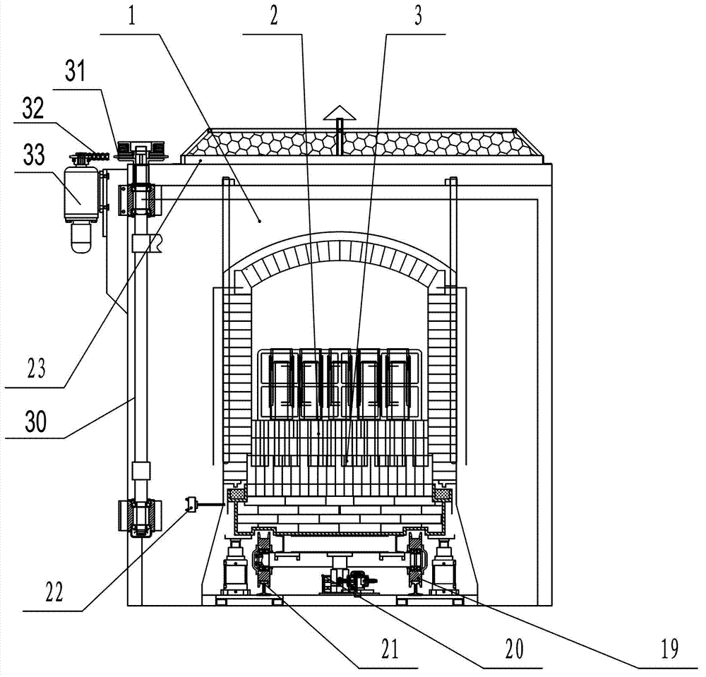
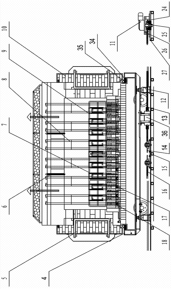
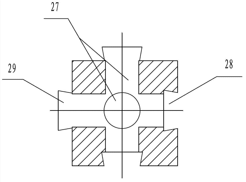
[0019] The specific implementation manner of the present invention will be described in detail below in conjunction with the accompanying drawings and preferred embodiments. Such as Figure 1 to Figure 3 Shown: a high-temperature sintering furnace, including a furnace body 1 with heating rods 8, a workpiece car 4 arranged at the bottom of the furnace body, a driving mechanism for driving the workpiece car, and a lifting mechanism for lifting the workpiece car , the lifting mechanism in the present invention is preferably a hydraulic cylinder 12 . The workpiece car bottom is provided with four wheels 19, and the wheels run on rails 21 fixed on the ground. In order to make the heating and cooling of the TC bearing uniform, the upper part of the workpiece car is tiled with refractory bricks 3 along the length direction of the workpiece car. The upper part of the refractory bricks is provided with hollow refractory bricks. Through holes 27 are respectively provided in the radial...


PUM


Abstract

The invention relates to the technical field of sintering furnaces, and in particular relates to a high-temperature sintering furnace. The high-temperature sintering furnace comprises a furnace body with a heating bar, a workpiece vehicle, a driving mechanism and a lifting mechanism, wherein the workpiece vehicle is arranged at the bottom of the furnace body; the driving mechanism is used for driving the workpiece vehicle to travel; and the lifting mechanism is used for lifting the workpiece vehicle. The high-temperature sintering furnace is characterized in that refractory bricks are tiled at the upper part of the workpiece vehicle along the length direction of the workpiece vehicle; the upper parts of the refractory bricks are provided with hollow refractory bricks; and the hollow refractory bricks are axially and radially provided with through holes respectively. The refractory bricks and the hollow refractory bricks are arranged on the workpiece vehicle, because the through holes are arranged in the hollow refractory bricks, each part of a TC (tungsten carbide) bearing can obtain uniform heat during the heating process, meanwhile, the bottom of the TC bearing in cooling can be cooled down uniformly, the product quality and amount are improved by 50% above, the product hardness is 260-280 degrees, and the ovality is reduced by 40% above.

Description

technical field [0001] The invention relates to the technical field of sintering furnaces, in particular to a high-temperature sintering furnace. Background technique [0002] TC bearings are the core components of screw drilling tools and need to have high wear resistance, so the requirements for their hardness are more stringent during the manufacturing process. At present, the manufacture of TC bearings is mainly fired in a sintering furnace. The high-temperature sintering furnace in the prior art includes a furnace body. A through furnace chamber is formed in the middle of the furnace body. Furnace doors are provided at both ends of the furnace chamber. A heating device for heating the furnace chamber and a workpiece car for carrying and processing TC bearings are provided on one side wall. The workpiece car is slidably arranged in the furnace chamber, and lifting mechanisms for lifting the workpiece car are provided on both sides of the furnace chamber. When in use, dr...

Claims


Application Information

Patent Timeline
IPC IPC(8): F27B5/04F27B5/14F27B5/06F27D3/12
Inventor 王振文
Owner TIANJIN LILIN GASOLINEEUM MACHINERY
Why Eureka
Try Eureka