
Fiber sintering type micro heat pipe and manufacturing method thereof

A manufacturing method and sintering technology, applied in the field of microelectronics, can solve the problems of heat pipe heat transfer performance decline, poor anti-gravity performance, complex processing technology, etc., and achieve good heat and mass transfer performance, high porosity, and simple processing technology Effect

Inactive Publication Date: 2012-01-04
SOUTH CHINA UNIV OF TECH
View PDF8 Cites 25 Cited by
  • Summary
  • Abstract
  • Description
  • Claims
  • Application Information

AI Technical Summary

Problems solved by technology

However, the capillary pressure is small, the groove depth and width are very high, and the directionality is very strong. When the heat pipe is bent greatly, the heat transfer performance of the heat pipe is greatly reduced, the anti-gravity performance is poor, and its processing technology is complicated.

Method used


Image

  • Fiber sintering type micro heat pipe and manufacturing method thereof
  • Fiber sintering type micro heat pipe and manufacturing method thereof
  • Fiber sintering type micro heat pipe and manufacturing method thereof

Examples


Embodiment

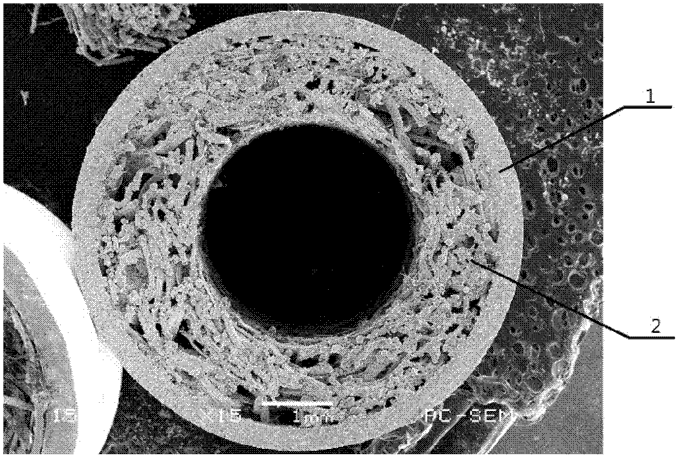
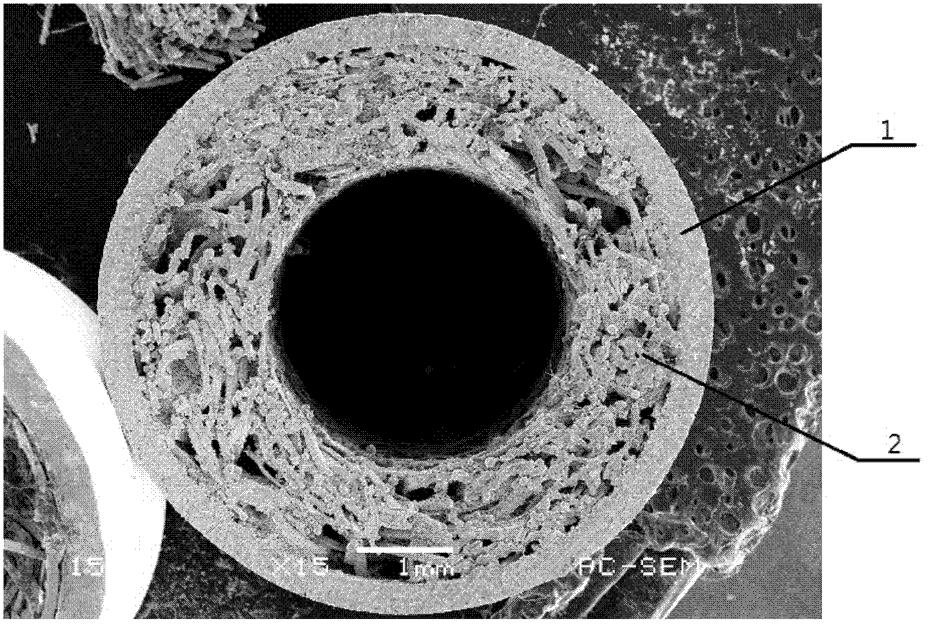
[0029] Such as figure 1 , figure 2 As shown, the fiber sintered micro heat pipe of the present invention comprises a base pipe 1, a liquid-absorbing core 2 and a liquid working medium filled in the liquid-absorbing core, the liquid working medium is any one of pure water, methanol, ethanol or acetone, and the base The inside of the tube 1 is evacuated, and both ends are closed structures. The base pipe 1 is a round metal pipe with an outer diameter of about 5 mm to 10 mm and a wall thickness of 0.2 mm to 0.5 mm. The liquid-absorbing core 2 is an annular metal fiber tube closely attached to the inner wall of the base pipe 1, the thickness of the liquid-absorbing core is about 0.3mm-0.5mm, and the porosity is about 65%-90%. The material used for the base pipe 1 can be red copper, aluminum alloy or stainless steel. The fiber used in the metal fiber tube can be copper fiber, aluminum fiber or stainless steel fiber.

[0030] The manufacturing method of the above-mentioned fibe...


PUM

PropertyMeasurementUnit
thicknessaaaaaaaaaa
thicknessaaaaaaaaaa
diameteraaaaaaaaaa

Abstract

The invention discloses a fiber sintering type micro heat pipe and a manufacturing method thereof. The fiber sintering type micro heat pipe consists of a base pipe, a liquid suction core and a liquid working medium, wherein the liquid suction core is formed by solid-phase sintering for metal fibers. The manufacturing method for the fiber sintering type micro heat pipe mainly comprises four steps, namely preparation for the base pipe, processing of the metal fibers, manufacturing of the liquid suction core and precise encapsulation for the liquid suction core. After the metal fibers are sintered, metallurgical bonding is realized among the fibers and a large quantity of multi-scale pore structures are formed. The fiber sintering type micro heat pipe manufactured by using the method has the advantages of simple process, low cost, high porosity and controllability of the liquid suction core, high permeability, small liquid reflux resistance, large specific surface area of a metal fiber sintering layer, high capillary force and the like, and a stable three-dimensional meshed porous structure is formed among the fibers, so the fiber sintering type micro heat pipe is difficult to damage.

Description

technical field [0001] The invention relates to micro heat pipe technology in the field of microelectronics, in particular to a fiber sintered micro heat pipe and a manufacturing method thereof. Background technique [0002] With the development trend of miniaturization and high integration of optoelectronic / microelectronic chips and their application systems, fatal problems such as narrow heat dissipation space and high heat flux density are caused. The traditional method of simply increasing the heat dissipation area by increasing the volume, weight and specific surface area of ​​the aluminum / copper heat sink is difficult to meet the requirements of further development in the future. Therefore, to solve the problem of thermal control of chips with high heat flux density in small spaces, more efficient heat dissipation must be adopted. way to replace the conventional air forced convection cooling technology. [0003] Micro heat pipes with high thermal conductivity, good is...

Claims


Application Information

Patent Timeline
Patent Type & Authority Applications(China)
IPC IPC(8): F28D15/04
Inventor 万珍平刘彬徐燕小李耀超
Owner SOUTH CHINA UNIV OF TECH
Learn More