
Double-spectrum imaging device driven by laser to generate X-ray source

A laser-driven, imaging device technology, applied in measuring devices, optical radiation measurement, spectrometry/spectrophotometry/monochromator, etc., to achieve the effects of easy installation, increased total brightness, and increased laser power density

Inactive Publication Date: 2012-11-14
INST OF FLUID PHYSICS CHINA ACAD OF ENG PHYSICS
View PDF4 Cites 10 Cited by
  • Summary
  • Abstract
  • Description
  • Claims
  • Application Information

AI Technical Summary

Problems solved by technology

Although the X-ray spectrum space generated by the laser-driven foil target is approximately distributed in a 4π solid angle, due to the limitation of the space layout of the vacuum target chamber in the experiment, the bremsstrahlung line or the characteristic radiation line can only be used alone, that is, either only the bremsstrahlung lines, or use only characteristic radiation lines

Method used


Image

  • Double-spectrum imaging device driven by laser to generate X-ray source
  • Double-spectrum imaging device driven by laser to generate X-ray source
  • Double-spectrum imaging device driven by laser to generate X-ray source

Examples


Embodiment 1

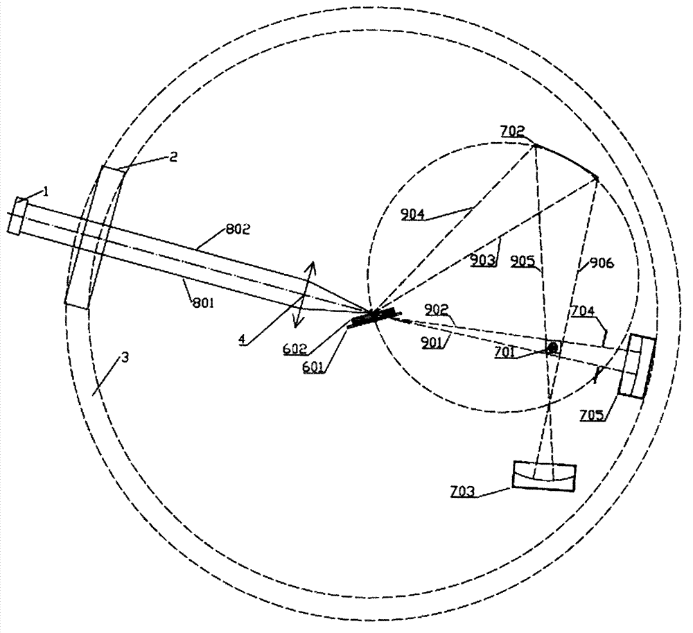
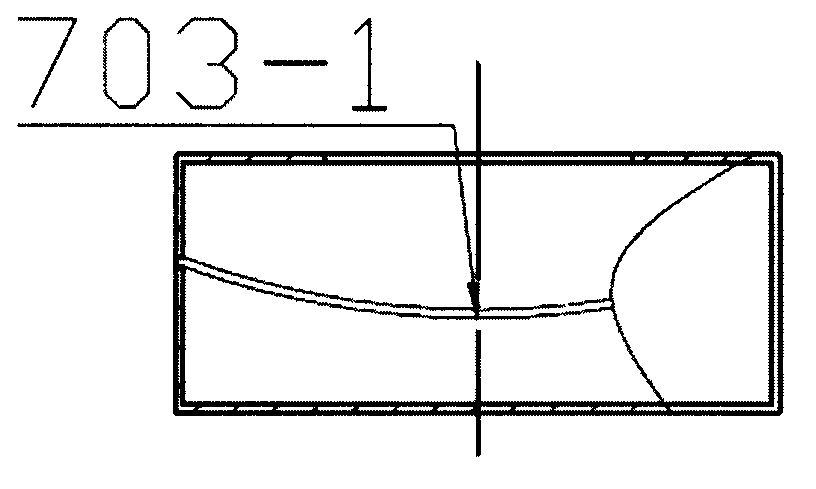
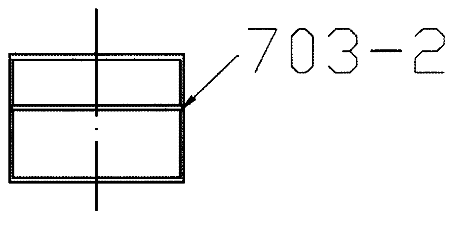
[0030] Embodiment one: if figure 1 , figure 2 , image 3 and Figure 4 , a dual-spectrum imaging device driven by laser to generate X-ray light source, including a laser 1, a vacuum chamber 3, a driving laser inlet 2 arranged on the vacuum chamber 3 and matched with the laser 1, and a target assembly installed in the vacuum chamber 3 , the target assembly is composed of a planar foil target 601 and a bracket 602, and the planar foil target 601 is located in the middle of the vacuum chamber 3, and the plane where the planar foil target 601 is located divides the vacuum chamber 3 into a space in front of the target and a space behind the target, which is characterized in that:

[0031] A spherical curved crystal 702 with diffraction characteristic radiation lines is fixed in the space in front of the target, a sample holder 701, a characteristic radiation line imager 703, a bremsstrahlung line imager 705 are fixed in the space behind the target, a planar foil target 601, a sp...

Embodiment 2

[0041] Embodiment two: if Figure 5 , the second experimental scheme of the dual energy spectrum experiment. A sample holder 701, a characteristic radiation line imager 703, and a bremsstrahlung line imager 705 are fixed in the space in front of the target, a spherical curved crystal 702 with diffraction characteristic radiation lines is fixed in the space behind the target, a planar foil target 601, a spherical surface The curved crystal 702, the sample holder 701, and the characteristic radiation line imager 703 constitute the characteristic radiation line optical path device, and the planar foil target 601, the sample holder 701, and the bremsstrahlung line imager 705 constitute the bremsstrahlung line optical path device, and The sample holder 701 is also located at the intersection of the diffraction optical path of the characteristic radiation spectral line downstream of the spherical curved crystal 702 and the transmission optical path of the bremsstrahlung spectral lin...


PUM


Abstract

A double-spectrum imaging device driven by laser to generate an X-ray source comprises a laser device (1), a vacuum chamber (3),a driving laser inlet (2) and a target assembly. The driving laser inlet (2) is arranged on the vacuum chamber (3) and is matched with the laser device (1), the target assembly is arranged in the vacuum chamber (3) and consists of a plane foil target (601) and a support (602), the plane foil target (601) is positioned in the middle of the vacuum chamber (3), andthe plane with the plane foil target (601) divides the vacuum chamber (3) into target-front space and target-rear space. The double-spectrum imaging device is characterized in that spherical bent crystals capable of being gathered are distributed at the front or the rear of the target to diffract X-rays, to-be-measured samples are distributed on a sample support (701) at the downstream of the spherical bent crystals, and backlight imaging information is received by an imager; and bremsstrahlung spectral lines are led to the front or the rear of the target to directly transmit through the to-be-measured samples on the sample support, and backlight imaging information is received by an imager at a signal receiving end.

Description

technical field [0001] The invention is a device for transmission imaging by using a laser to drive a solid material to generate characteristic spectral lines (characteristic radiation spectral lines) and continuous spectral lines (bremsstrahlung spectral lines). Background technique [0002] The X-ray source generated by the interaction between laser and solid matter covers a wide range of wavelengths, from vacuum ultraviolet to high-energy hard X-rays. The most studied X-spectrum is the high-energy bremsstrahlung line and the characteristic radiation line of the material, both of which have the characteristics of small spot, high photon energy, and short pulse time, so they are often used in high-energy density physical processes. Diagnostic studies such as backlight imaging diagnosis of implosion processes or pinch processes. Among them, the non-thermal radiation effect of the K-shell characteristic radiation line has high energy conversion efficiency and its own narrow ...

Claims


Application Information

Patent Timeline
IPC IPC(8): G01J3/28G01J3/02
Inventor 王洪建叶雁李军阳庆国李晓亚朱鹏飞刘振清朱巍李泽仁
Owner INST OF FLUID PHYSICS CHINA ACAD OF ENG PHYSICS
Learn More