Modular bypass vent waste heat boiler at tail of cement kiln

A bypass exhaust, waste heat boiler technology, applied in furnaces, waste heat treatment, furnace components, etc., can solve the problems of heat exchange efficiency affecting the power generation efficiency of waste heat power plants, difficult welding quality control, and large welding workload, etc., to simplify the site. The effect of installation process, labor cost saving, and installation cost saving

Inactive Publication Date: 2012-11-21
DALIAN EAST NEW ENERGY DEV
View PDF7 Cites 9 Cited by
  • Summary
  • Abstract
  • Description
  • Claims
  • Application Information

AI Technical Summary

Problems solved by technology

The above installation steps require a dozen or even dozens of welders to perform a large number of welding operations in an open-air working environment. The welding workload is heavy, the welding difficulty is high, and the welding quality is difficult to control.
The heat exchange efficiency of the boiler directly affects the power generation efficiency of the waste heat power station, and the installation quality of the bypass ventilation boiler determines the efficiency of the boiler. Due to the delivery of parts, the construction site conditions are poor, and the open-air construction is subject to seasonal and climatic conditions. It is easy to cause hidden dangers in quality and affect boiler efficiency

Method used


Image

  • Modular bypass vent waste heat boiler at tail of cement kiln
  • Modular bypass vent waste heat boiler at tail of cement kiln
  • Modular bypass vent waste heat boiler at tail of cement kiln

Examples


Embodiment 1

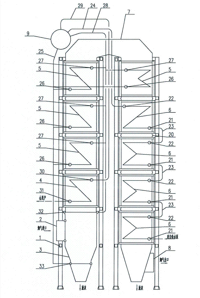
[0016] exist figure 1 In the schematic diagram of the front view of the cement kiln kiln tail modular bypass venting waste heat boiler shown in Example 1, the bypass venting boiler in an inverted "U" shape includes the following components: steel frame platform 1, flue gas inlet 2 , water wall 3, superheater module 4, evaporator module 5, economizer module 6, steering flue 7, flue gas outlet 8 and drum 9. Among them, the superheater module, evaporator module and economizer module have the same structure, such as Figure 4 As shown, they each have an independent frame 10, and the frame is surrounded by a heat-insulating guard plate 11 to form a section of a cylindrical outer shell. The guard plate is double-layered, and insulating materials are filled between the guard plates. ; The frame is provided with a ventilation mechanism 13; the frame is also provided with 2 pairs of hoisting mechanisms 14; the heating surfaces 15 of the superheater module, the evaporator module and th...

Embodiment 2

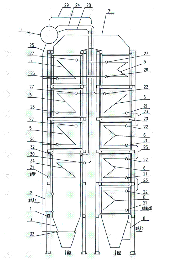
[0019] exist figure 2 In the schematic diagram of the front view of the cement kiln tail modular bypass venting waste heat boiler shown in Example 2, the bypass venting boiler in an inverted "U" shape includes the following components: steel frame platform, flue gas inlet, water cooling Wall, superheater parts 34, evaporator module, economizer module, steering flue, flue gas outlet and drum. Among them, the evaporator module and the economizer module have the same structure, such as Figure 4 As shown, they each have an independent frame, and the frame is surrounded by a heat-insulating guard plate to form a cylindrical shell. The guard plate is double-layered, and the insulating material is filled between the guard plates. There is a ventilation mechanism; there are also two pairs of hoisting mechanisms on the frame; the heating surfaces of the evaporator module and the economizer module are set on the frames in their respective shells; they are connected to the heating sur...

Embodiment 3

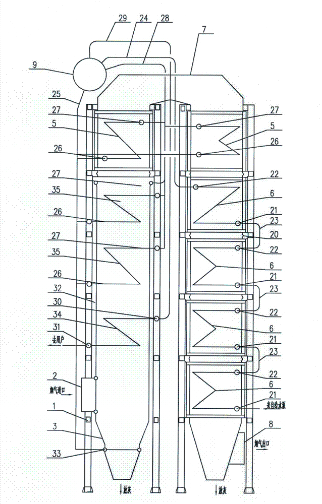
[0022] exist image 3 In the schematic diagram of the front view of the cement kiln tail modular bypass venting waste heat boiler shown in Example 3, the bypass venting boiler in an inverted "U" shape includes the following components: steel frame platform, flue gas inlet, water cooling Wall, superheater parts, evaporator parts 35, evaporator module, economizer module, steering flue, flue gas outlet and drum. Among them, the evaporator module and the economizer module have the same structure, such as Figure 4 As shown, they each have an independent frame, and the frame is surrounded by a heat-insulating guard plate to form a cylindrical outer shell. The guard plate is double-layered, and the insulating material is filled between the guard plates. There is a ventilation mechanism; 2 pairs of hoisting mechanisms are provided on the frame; the heating surfaces of the evaporator module and the economizer module are all set on the frames in the respective shells; they are connect...


PUM


Abstract

A modular bypass vent waste heat boiler at the tail of a cement kiln is mainly characterized in that a part of heating surfaces adopts heating surface modules which are independent of one another, have the same structure and is provided with respective independent frames; heat insulation protection plates are arranged around the frames to form a section of cylindrical outer shell; hoisting mechanisms are arranged on the frames; the heating surfaces of the modules are arranged on the frames in the respective outer shells; one end of each of inlet/outlet headers connected with the heating surfaces of the modules is arranged outside the outer shell; upper components of the boiler are connected with lower components of the boiler; and upper and lower headers of the modules are connected with ascending and descending pipes of a boiler barrel by pipelines as required. The installation period of the waste heat boiler can be greatly shortened, the labor cost is saved, the installation cost is greatly lowered, the welding quality can be controlled better, the service life of the boiler can be prolonged, and the heating surface of the boiler can be prevented from damages in the transportation process to the full extent.

Description

technical field [0001] The invention relates to a waste heat boiler, in particular to a cement kiln tail bypass waste heat boiler. Background technique [0002] In the cement kiln system, the composition of raw materials and fuels has a great influence on the system. In order to prevent the system from malfunctions such as skinning and blockage, a part of the gas from the kiln tail smoke chamber to the rising flue of the calciner is released through technical means. On the one hand, it can effectively To alleviate the occurrence of failures, on the other hand, this part of the flue gas can be passed through the bypass boiler to heat water into steam for power generation. At present, the bypass ventilation boiler adopts the method of delivery of parts and on-site installation. The installation period is 3 months, and it requires a lot of manpower and material support. The on-site installation process of the main heating surface of the bypass ventilation boiler is as follows:...

Claims


Application Information

Patent Timeline
Patent Type & Authority Applications(China)
IPC IPC(8): F22B1/18F27D17/00
CPCY02P10/25
Inventor 唐金泉金万金孙明朗庄宇刚林琳
Owner DALIAN EAST NEW ENERGY DEV
Why Eureka
Try Eureka