Method for producing liquid crystal display panel

A technology for a liquid crystal display panel and a manufacturing method, which is applied in semiconductor/solid-state device manufacturing, optics, instruments, etc., can solve the problems of high cost, complex manufacturing process, low yield, etc., and achieves good film-forming performance, simplified process, and flat adhesion. effect of action

Active Publication Date: 2012-11-28
TCL CHINA STAR OPTOELECTRONICS TECH CO LTD
View PDF4 Cites 20 Cited by
  • Summary
  • Abstract
  • Description
  • Claims
  • Application Information

AI Technical Summary

Problems solved by technology

The manufacturing process is more complicated, the cost is relatively high, and the yield rate is low

Method used


Image

  • Method for producing liquid crystal display panel
  • Method for producing liquid crystal display panel
  • Method for producing liquid crystal display panel

Examples


Embodiment Construction

[0039] In order to further illustrate the technical means adopted by the present invention and its effects, the following describes in detail in conjunction with preferred embodiments of the present invention and accompanying drawings.

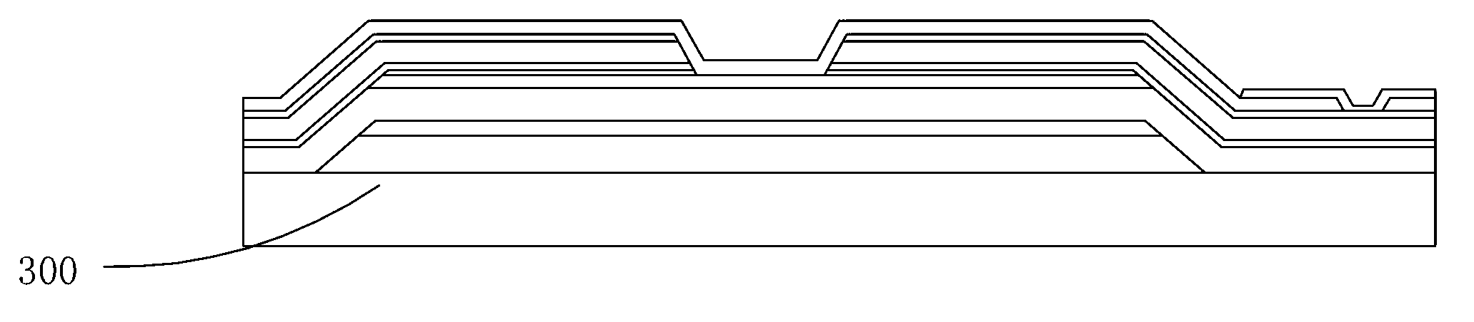
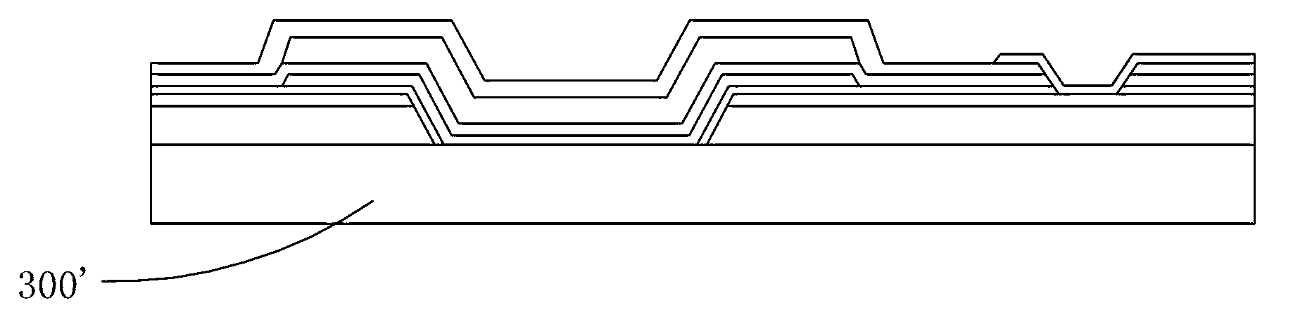
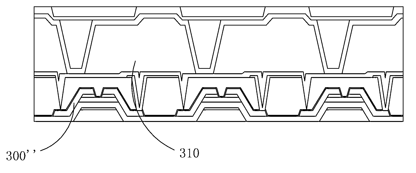
[0040] see Figure 4 to Figure 17 , the invention provides a method for manufacturing a liquid crystal display panel, comprising the following steps:

[0041] Step 1, providing a substrate 20 .

[0042] The substrate 20 is a transparent substrate, and in this embodiment, the substrate 20 is a glass substrate.

[0043] Step 2, forming a black photoresist material layer on the substrate 20, and forming a predetermined pattern through a photomask process, and then forming a black matrix 22 (such as Figure 5 shown).

[0044] The black photoresist layer can be formed on the substrate 20 by printing, printing or coating. The photomask process includes processes such as exposure, development, and etching.

[0045] Step 3, forming an isolation l...


PUM


Abstract

The invention provides a method for producing a liquid crystal display panel, which comprises the following steps: 1, providing a substrate; 2, forming a black photoresist layer on the substrate, forming a preset pattern through a photomask process, and further producing a black matrix; 3, forming an isolating layer on the black photoresist layer; 4, producing a first metal layer on the isolating layer, forming a second metal layer on the first metal layer, forming the preset pattern through the photomask process, and furthermore, forming a source / drain electrode and a storage capacitor Com electrode; 5, forming an ohmic contact layer on the second metal layer, forming the preset pattern through the photomask process, and furthermore, forming a doped phosphorus film on a metal electrode; 6, arranging a channel layer on the ohmic contact layer, forming the preset pattern through the photomask process, and thus forming an island; 7, forming a gate insulation layer on the channel layer, arranging a third metal layer on the gate insulation layer, forming the preset pattern through the photomask process, furthermore, forming a grid and a storage capacitor counter electrode, and arranging a storage capacitor at the edge position of the black matrix; 8, forming a protective layer on the third metal layer; 9, forming right (R), green (G) and blue (B) pixels on the protective layer; 10, forming via holes in the positions of the R, G and B pixels, which correspond to the source electrode and the storage capacitor; 11, arranging a transparent electric conduction layer on the R, G and B pixels, forming the preset pattern through the photomask process, furthermore, forming a pixel electrode, and thus forming a color filter on array (COA) substrate; and 12, bonding the COA substrate with an upper substrate, filling liquid crystal into the COA substrate and the upper substrate, and thus forming the liquid crystal display panel.

Description

technical field [0001] The invention relates to the field of liquid crystal display, in particular to a method for manufacturing a liquid crystal display panel. Background technique [0002] A liquid crystal display (LCD, Liquid Crystal Display) has many advantages such as a thin body, power saving, and no radiation, and has been widely used. Most of the liquid crystal display devices currently on the market are backlight liquid crystal display devices, which include a liquid crystal display panel and a backlight module. The working principle of the liquid crystal display panel is to place liquid crystal molecules between two parallel glass substrates, and control the liquid crystal molecules to change direction through whether the glass substrates are energized or not, and refract the light from the backlight module to produce a picture. [0003] Usually, the liquid crystal display panel consists of a color filter substrate (CF, Color Filter), a thin film transistor substr...

Claims


Application Information

Patent Timeline
Patent Type & Authority Applications(China)
IPC IPC(8): G02F1/1333G02F1/136H01L21/77
CPCG02F1/136209G02F1/136213G02F1/136227G02F1/136222H01L27/1262H01L29/78633
Inventor 戴超
Owner TCL CHINA STAR OPTOELECTRONICS TECH CO LTD
Why Eureka
Try Eureka