Cathode-adjustable single anode magnetic control electron gun

A magnetron electron gun, adjustable technology, applied to the electron/ion gun of the transit time type electron tube, etc., can solve the problems of inability to adjust, the efficiency of the injection-wave interaction is reduced, and the initial speed of the electron is discretely increased, and the reduction is achieved. Equipment error and thermal deformation, excellent performance, and the effect of reducing discreteness

Inactive Publication Date: 2012-11-28
UNIV OF ELECTRONICS SCI & TECH OF CHINA
View PDF3 Cites 13 Cited by
  • Summary
  • Abstract
  • Description
  • Claims
  • Application Information

AI Technical Summary

Problems solved by technology

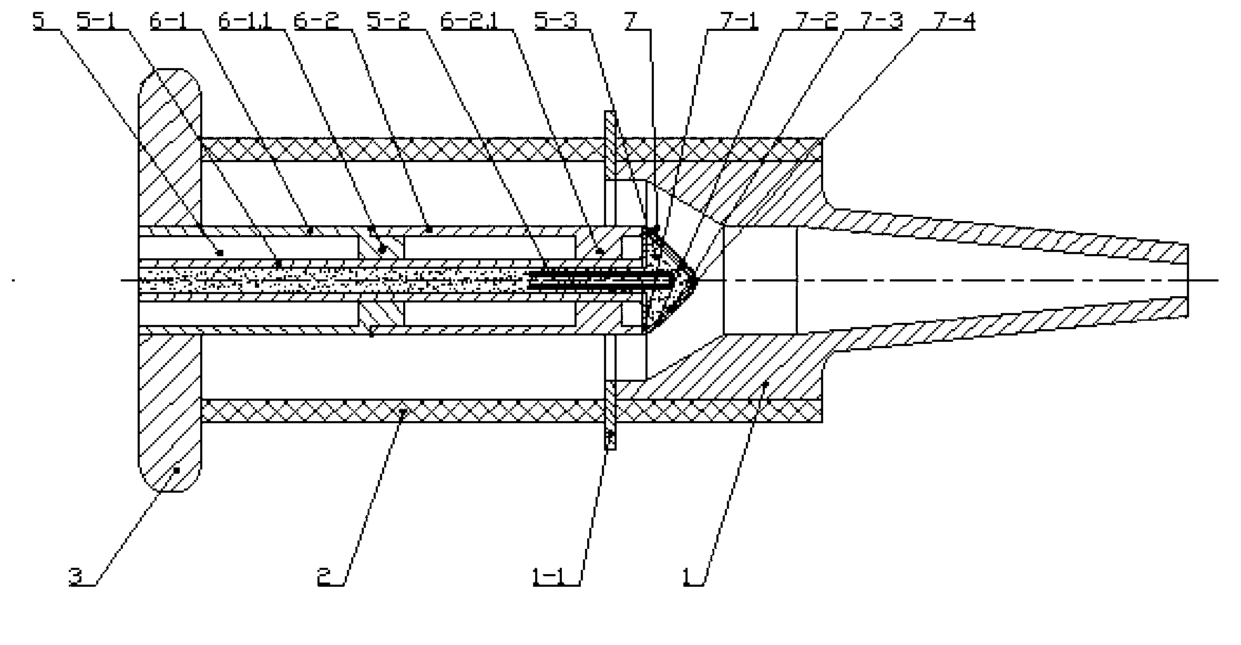
The rear part of the support cylinder in the electron gun is fastened in the center hole of the base, the heating wire assembly is fixed on the axis in the electron gun shell through the support cylinder, and the cathode of the electron gun is fastened to the front end of the heating wire sleeve through its fixing ring plate. The rear part of the anode of the electron gun is embedded in the inner wall of the front part of the electron gun housing and covered on the cathode, and is fastened to the housing through its fixing ring (see attached figure 1 ); although the electron gun has a relatively simple structure, since the heating wire assembly and the cathode of the electron gun are fastened into one body thro...

Method used


Image

  • Cathode-adjustable single anode magnetic control electron gun
  • Cathode-adjustable single anode magnetic control electron gun
  • Cathode-adjustable single anode magnetic control electron gun

Examples


Embodiment Construction

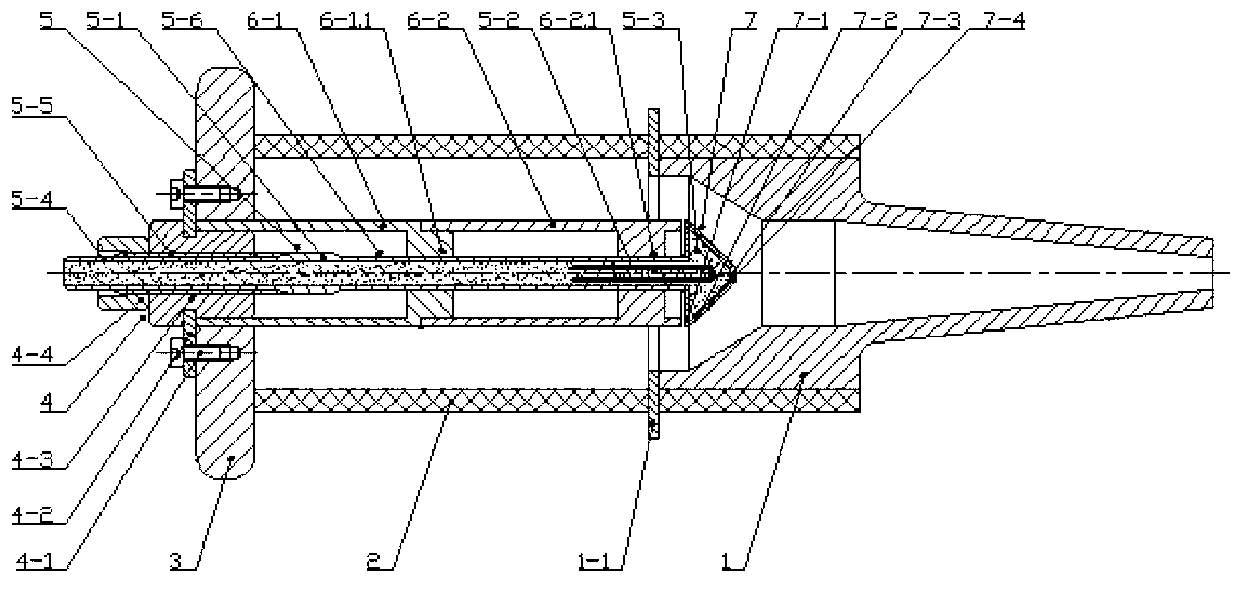
[0012] This embodiment: the total length is 283mm, the anode 1. The axial length is 136mm, the outer diameter of the rear part is Φ57mm, the diameter of the middle part is Φ26mm, the front length is 86mm, the inclination angle of the cone annulus at the rear part (covered on the cathode) is 32°, and the taper of the front part is 11 °, shell 2. outer diameter Φ68mm, length 150mm, wall thickness 5.5mm, base 3. outer diameter Φ102mm, thickness 15mm, center hole diameter Φ27mm; heating wire assembly 5: heating wire sleeve 5-1 length 152mm, outer Diameter Φ10mm, wall thickness 1.0mm, upper scale section 5-4 outer diameter Φ9.0mm (wall thickness 0.5mm), axial length 10mm, adjusting thread 5-5 adopts G10 fine tooth pipe thread, thread section length 45mm, The guide plane 5-6 in this embodiment is made of two arc-shaped cylinders with a symmetrical grinding height of 0.2mm on the upper and lower sleeves before the length of the thread section; the resistance of the heating wire 5-2 is...


PUM


Abstract

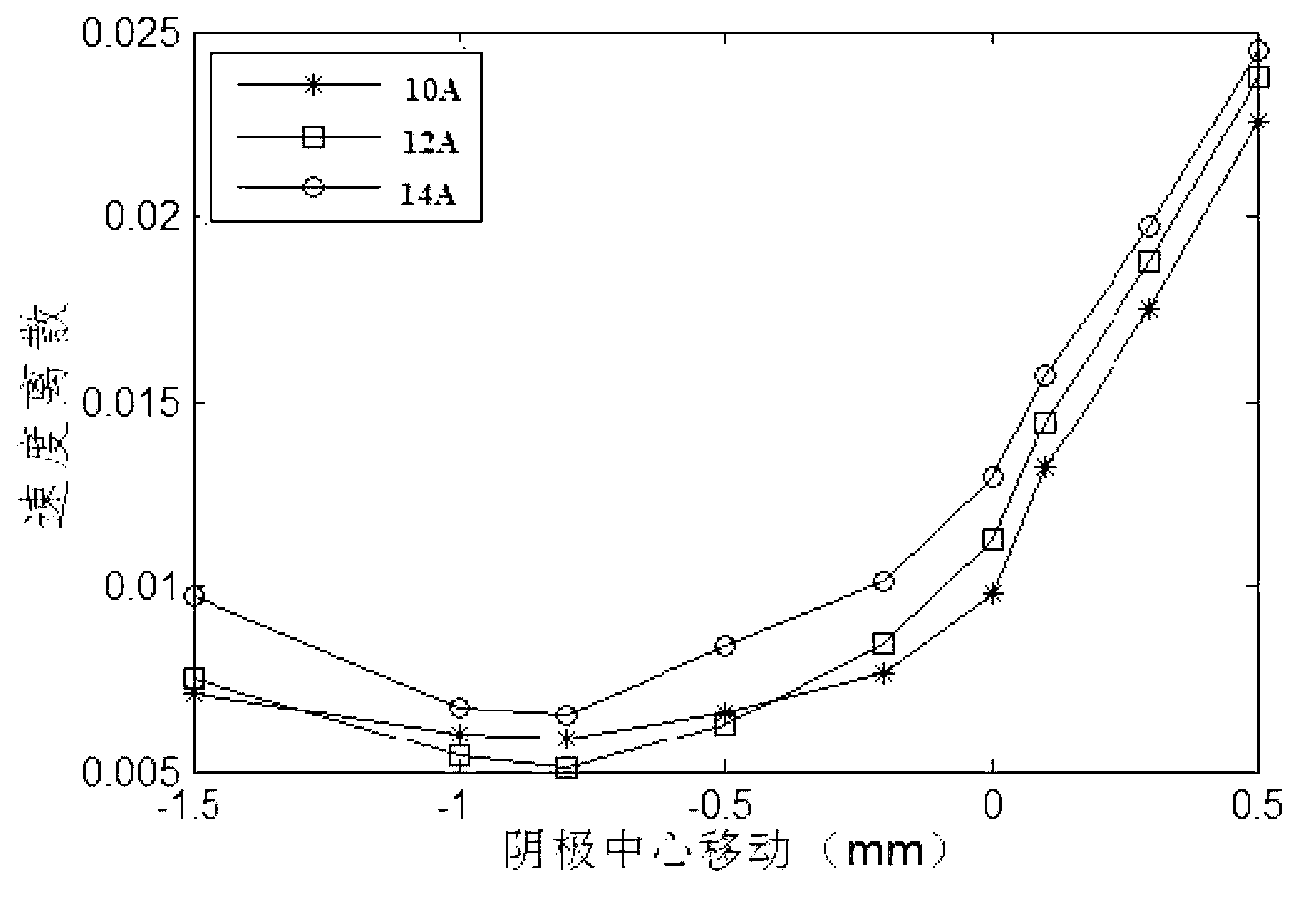
A cathode-adjustable single anode magnetic control electron gun belongs to a single anode magnetic control electron gun that is used in conjunction with a vacuum gyrotron, and comprises an electron gun casing, a base, an electric heating wire component, a support cylinder, a regulating mechanism assembly, an electron gun cathode, a fixed annular plate, an anode and a retainer ring, wherein, the electric heating wire component comprises an electric heating wire, an electric heating wire sleeve and insulating fillers, and the electric heating wire sleeve is provided with a ring-shaped scale section, a threaded section and a guiding plane surface; the regulating mechanism assembly is arranged between the electric heating wire sleeve and the support cylinder thereof, and comprises an adjusting screw nut; in addition, the cathode-adjustable single anode magnetic control electron gun can adjust the distance between the cathode and anode according to the operating condition, the transverse to longitudinal velocity ratio of an obtained electron beam is greater than 1.0, and the longitudinal velocity spread is less than 2 percent. Therefore, the influence caused by assembly error and overheating deformation or great current and voltage variation of the electron gun can be overcome effectively, and the cathode-adjustable single anode magnetic control electron gun is characterized in that working current and voltage capable of adapting to wider range can be achieved, the discreteness of the electronic longitudinal velocity is low, the performance of the electron beam is excellent, and the power and the efficiency for later beam-wave interaction of the gyrotron can be improved and so on.

Description

technical field [0001] The invention belongs to the single-anode magnetron electron gun in the technical fields of high-power microwave, millimeter wave and submillimeter wave, in particular to a cathode-adjustable single-anode magnetron electron gun matched with a vacuum gyrotron. Background technique [0002] High-power gyrotron plays an extremely important role as a high-power microwave source. With the research of gyrotron in millimeter-wave radar, communication, and high-power microwave weapons, especially controlled thermonuclear fusion, the attractiveness of high-energy physics and industry Prospects have promoted the development of the gyrotron, and the requirements for the power and efficiency of the gyrotron are getting higher and higher. Since the quality of the electron beam has a great influence on the interaction efficiency of the gyrotron injector wave, the helical electron beam provided by the gyrotron magnetron injection gun (MIG) must satisfy the following ...

Claims


Application Information

Patent Timeline
IPC IPC(8): H01J23/06
Inventor 鄢然罗勇屈晓斌王丽王建勋李焱昭
Owner UNIV OF ELECTRONICS SCI & TECH OF CHINA
Why Eureka
Try Eureka