
Re-combustion hot gas generating furnace

A technology of hot gas generation and generator, applied in the direction of combustion method, combustion equipment, fuel supply, etc., which can solve the problems of not meeting environmental protection requirements, unrealizable fluidity, and lack of volume

Inactive Publication Date: 2012-12-05
ZHENGZHOU DINGLI DRYING EQUIP
View PDF5 Cites 4 Cited by
  • Summary
  • Abstract
  • Description
  • Claims
  • Application Information

AI Technical Summary

Problems solved by technology

[0004] The process of the traditional furnace heating system is: first ignite the coal that enters the furnace body, and then use the calorific value of the ignited coal to gradually ignite the subsequent coal. Burn out quickly and easily form a burning coking layer on its surface, and the coking layer has an airtight enveloping core, so that the lower part of the layer lacks oxygen and cannot be burned, resulting in energy waste due to incomplete combustion of coal blocks and does not meet environmental protection requirements
At the same time, the coal that has just entered the combustion pool is too large to be easily ignited. At this stage, the coal itself not only cannot generate heat, but also absorbs a large amount of heat from the surroundings, causing the system to generate a heat drop, which in turn causes the thermal instability of the system.
And in the subsequent combustion, along with the whole process of the coal from ignition to peak until exhaustion, the heat energy will also experience a sinusoidal fluctuation process from low to high and then to low, making the combustion unstable and difficult to achieve temperature control
On the other hand, the residue from coal burning cannot be automatically controlled due to its large volume and lack of fluidity.

Method used


Image

  • Re-combustion hot gas generating furnace
  • Re-combustion hot gas generating furnace
  • Re-combustion hot gas generating furnace

Examples


Embodiment Construction

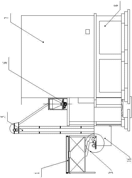
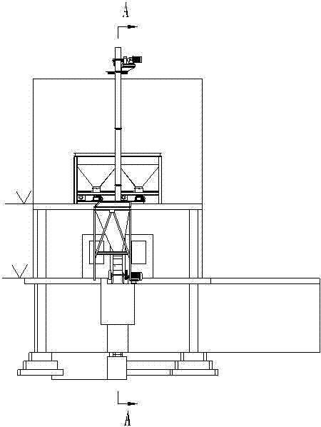
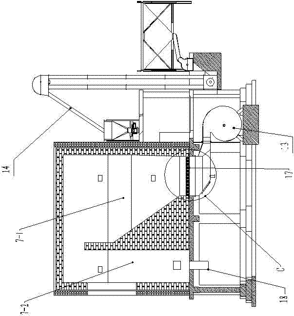
[0025] like figure 1 , 2 , 3, 4, 5, 6, 7, 8, a kind of post-combustion hot gas generator, including generator furnace body 7, also includes raw coal batching bin 1, bucket elevator 5, disc feeder 6, Blower 13, the bottom of the raw coal batching bin 1 is provided with a coal pulverizer 2 connected thereto, the coal pulverizer 2 communicates with the pulverized coal storage bin 16, and the pulverized coal storage bin 16 passes through the hopper Type hoist 5, chute 14 are communicated with disc feeder 6, and this disc feeder 6 is communicated with generator furnace body 7, and described generator furnace body 7 bottoms are provided with air inlet 17, and at air inlet The position 17 is provided with an air distribution plate 10, and the air distribution plate 10 is provided with a wind cap 9, and the air inlet 17 communicates with the blower 13 through the bellows 11.

[0026] The described generator furnace body 7 is fixedly arranged on the generator furnace body foundat...


PUM


Abstract

The invention relates to generating furnace equipment, in particular to a re-combustion hot gas generating furnace, which can meet the requirements of heat supply energy sources under various coal conditions. The re-combustion hot gas generating furnace comprises a generating furnace body, a raw material proportioning bin, a hopper type elevator, a rotary disc feeder and a blower, wherein the bottom of the raw material proportioning bin is provided with a coal grinder which is communicated with the raw material proportioning bin; the coal grinder is communicated with a coal powder storage bin; the coal powder storage bin is communicated with the rotary disc feeder through the hopper type elevator and a chute; the rotary disc feeder is communicated with the generating furnace body; the bottom of the generating furnace body is provided with an air inlet; an air distribution plate is arranged at the air inlet, and is provided with an air cap; and the air inlet is communicated with the blower through an air box. Due to the adoption of a novel autonomously-developed automatic re-combustion efficient heat energy generating furnace, the defects of unstable heat, difficulty in realizing automatic control, incomplete burning, adversity to energy saving and environment friendliness and the like caused by large size of burning coal briquette in the conventional process are overcome.

Description

technical field [0001] The invention relates to a generator equipment, in particular to a post-combustion hot gas generator capable of meeting the heat supply energy requirements under various coal quality conditions. Background technique [0002] The traditional heating system process is that the coal is burned in the furnace to generate heat to provide heat. The process has defects such as incomplete coal combustion, energy waste, environmental protection, unstable heat, small heat supply, and difficult to achieve temperature control and automatic operation. . [0003] In recent years, with the maturity of drying technology, drying equipment has been more and more widely used in national economic construction. As an emerging industry, drying equipment has become more and more prominent in the construction of the national economy. With the rapid development of industry technology, as a member of the army of drying equipment - the new automatic heat successor and high-effic...

Claims


Application Information

Patent Timeline
IPC IPC(8): F23C7/02F23K3/00F23J1/02
Inventor 李留纪罗刚银
Owner ZHENGZHOU DINGLI DRYING EQUIP
Learn More