

Device for Brillouin optical time domain reflectometer based on optical phase-locked ring
An optical time domain reflectometer and phase-locked loop technology, applied in spectrum investigation and other directions, can solve the problems of low measurement accuracy, unstable output, and inability to tune the output frequency, and achieve the effect of solving complex processing, reducing costs, and simplifying the system.
- Summary
- Abstract
- Description
- Claims
- Application Information
AI Technical Summary
Problems solved by technology
Method used
Image

Examples
specific Embodiment approach 1
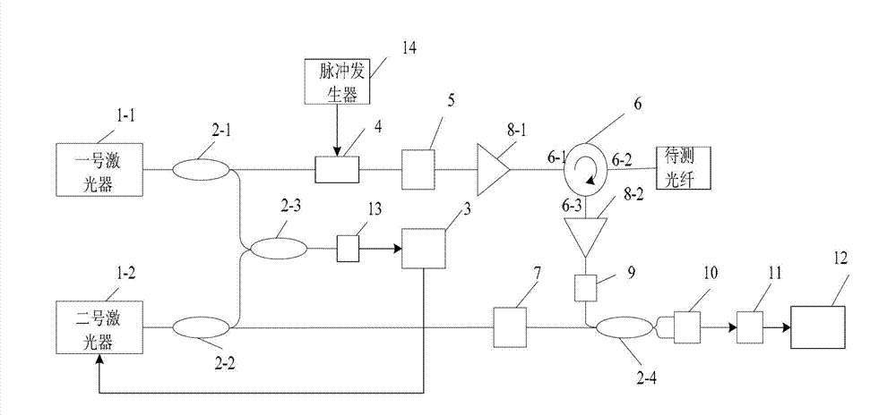
[0010] Specific implementation mode one: combine figure 1 Describe this embodiment, the device of the Brillouin optical time domain reflectometer based on the optical phase-locked loop described in this embodiment, it is made up of No. 1 laser 1-1, No. 2 laser 1-2, No. 1 fiber coupler 2- 1. No. 2 fiber coupler 2-2, No. 3 fiber coupler 2-3, No. 4 fiber coupler 2-4, phase-locked loop module 3, electro-optic modulator 4, polarization scrambler 5, circulator 6, optical Attenuator 7, No. 1 erbium-doped fiber amplifier 8-1, No. 2 erbium-doped fiber amplifier 8-2, optical filter 9, double-balanced detector 10, bandpass electric filter 11, data acquisition module 12, detection and amplification module 13 Composed of a pulse generator 14, the output end of the No. 1 laser 1-1 is connected with the optical signal input end of the No. 1 fiber coupler 2-1, and the optical signal output end of the No. 1 fiber coupler 2-1 is connected with the electro-optical modulator at the same time. 4 ...
specific Embodiment approach 2
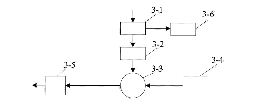
[0012] Specific implementation mode two: combination figure 2 Describe this embodiment, this embodiment is to further limit the device of the Brillouin optical time-domain reflectometer based on the optical phase-locked loop described in the specific embodiment one, the phase-locked loop module 3 is composed of a directional coupler 3-1, a frequency division device 3-2, phase / frequency discriminator 3-3, reference signal source 3-4, loop filter 3-5 and frequency counting unit 3-6, the electrical signal input terminal of directional coupler 3-1 is a lock The electrical signal input end of the phase loop module 3, the output end of a signal of the directional coupler 3-1 is connected with the input end of the signal of the frequency divider 3-2, and the output end of another signal of the directional coupler 3-1 is connected with The input end of the frequency counting unit 3-6 is connected; the output end of the signal of the frequency divider 3-2 is connected with a signal in...
specific Embodiment approach 3
[0015] Specific embodiment three: this embodiment is to further limit the device of the Brillouin optical time domain reflectometer based on the optical phase-locked loop described in the specific embodiment one, and the first laser 1-1 and the second laser 1-2 both use Single frequency narrow linewidth fiber laser, distributed feedback semiconductor laser or external cavity semiconductor laser.
PUM
 Abstract
Description
Claims
Application Information