Manufacturing method of resonant rod, resonant rod and cavity filter
A manufacturing method and technology of resonant rods, applied in the direction of resonators, waveguide devices, electrical components, etc., can solve the problems of limited application, coarse casting structure, high loss of raw materials, etc., to improve performance indicators and stability, reduce alloy composition deviation Accumulation, reduce the effect of raw material consumption
- Summary
- Abstract
- Description
- Claims
- Application Information
AI Technical Summary
Problems solved by technology
Method used
Image
Examples
Embodiment 1
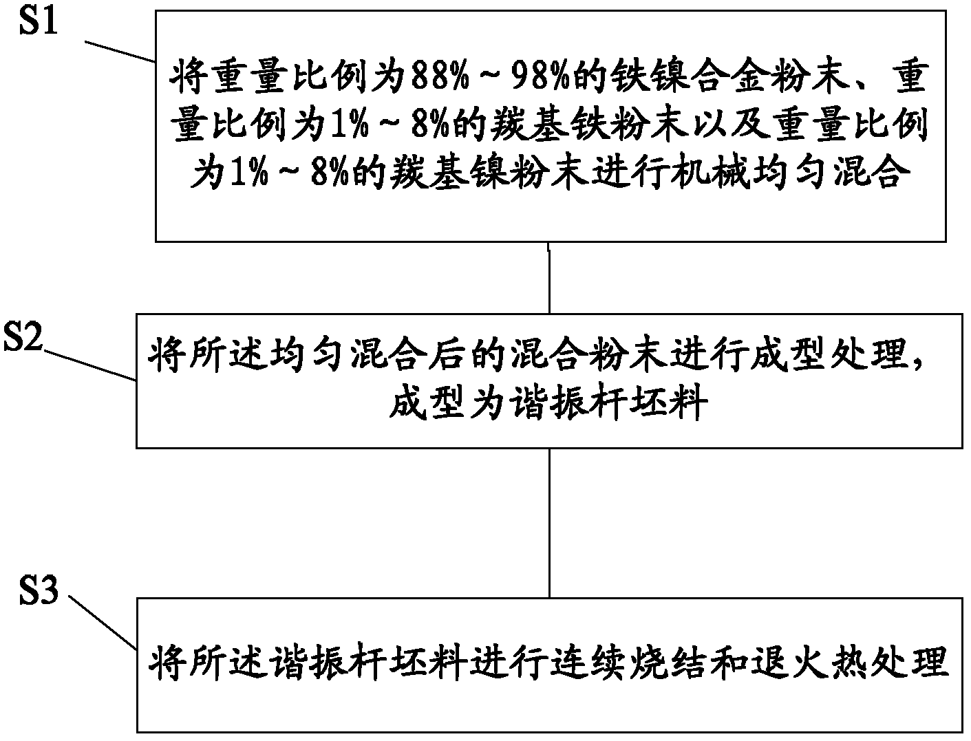
[0023] A method for manufacturing a resonant rod, the flow chart of which is as follows figure 1 shown, including:
[0024] Step S1, uniformly mechanically mixing 88%-98% iron-nickel alloy powder, 1%-8% carbonyl iron powder and 1%-8% carbonyl nickel powder by weight.
[0025] In the embodiment of the present invention, the weight ratio of the iron-nickel alloy powder is preferably 92-96%, the weight ratio of the carbonyl iron powder is preferably 2-4%, and the weight ratio of the carbonyl nickel powder is preferably 2-4%. Most preferably, the weight ratio of the iron-nickel alloy powder is 94%, the weight ratio of the carbonyl iron powder is 3%, and the weight ratio of the carbonyl nickel powder is 3%. It should be noted that the raw materials inevitably contain a small proportion of impurities such as carbon, nitrogen, sulfur and phosphorus, and generally the proportion of impurities is not more than 0.1%.
[0026] In the embodiment of the present invention, the iron-nickel...
Embodiment 2
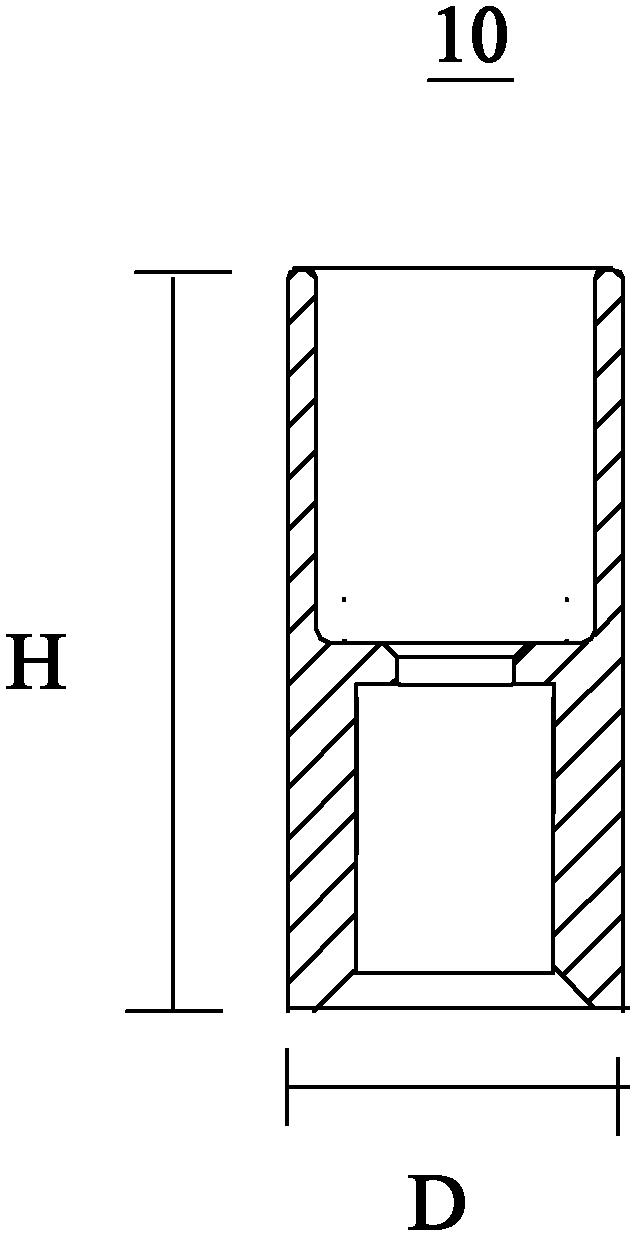
[0048] A kind of resonant bar 10, its structural schematic diagram is as figure 2 As shown, the height of the resonant rod is H, and the outer diameter is D. The resonant rod 10 includes iron-nickel alloy with a weight ratio of 88%-98%, carbonyl iron with a weight ratio of 1%-8%, and carbonyl nickel with a weight ratio of 1%-8%, and the iron-nickel alloy, carbonyl iron and Nickel carbonyl is pressed or injection molded into resonant rods.
[0049] Using the iron-nickel alloy, carbonyl iron and carbonyl nickel in the above ratio, the resonant rod is made by one-time molding process, which greatly reduces the loss of raw materials and saves the cost of machining
[0050] In the embodiment of the present invention, the weight ratio of iron-nickel alloy is preferably 92-96%, the weight ratio of iron carbonyl is preferably 2-4%, and the weight ratio of nickel carbonyl is preferably 2-4%. Most preferably, the weight ratio of iron-nickel alloy is 94%, the weight ratio of iron carb...
Embodiment 3
[0055] A resonant rod, which contains iron-nickel alloy with a weight ratio of 88%-98%, carbonyl iron with a weight ratio of 1%-8%, and carbonyl nickel with a weight ratio of 1%-8%, and the iron-nickel alloy, carbonyl iron It is uniformly mixed with nickel carbonyl in powder form and formed into a resonant rod.
[0056] In the embodiment of the present invention, the high-performance iron-nickel alloy microwave resonator rod is prepared by using uniformly mixed powder with iron-nickel alloy powder as the main body to form a resonator rod, which can minimize the segregation of alloy components and eliminate coarse and uneven Microstructural defects, thereby improving the performance index and stability of the corresponding products.
[0057] In a further embodiment of the present invention, the weight ratio of iron-nickel alloy is 92%-96%, the weight ratio of carbonyl iron is 2%-4%, and the weight ratio of carbonyl nickel is 2%-4%. The iron-nickel alloy contains 36% of nickel ...
PUM
| Property | Measurement | Unit |
|---|---|---|
| Grain size | aaaaa | aaaaa |
| Outer diameter | aaaaa | aaaaa |
| Height | aaaaa | aaaaa |
Abstract
Description
Claims
Application Information
 - R&D
- Intellectual Property
- Life Sciences
- Materials
- Tech Scout
- Unparalleled Data Quality
- Higher Quality Content
- 60% Fewer Hallucinations
Browse by: Latest US Patents, China's latest patents, Technical Efficacy Thesaurus, Application Domain, Technology Topic, Popular Technical Reports.
© 2025 PatSnap. All rights reserved.Legal|Privacy policy|Modern Slavery Act Transparency Statement|Sitemap|About US| Contact US: help@patsnap.com


